Description
This 2006-2016 Suzuki VZR1800 M109 Boulevard motorcycle Service Manual provides detailed service information, step-by-step repair instruction and maintenance specifications for Suzuki VZR1800 M109 Boulevard Motorcycles.
Model Year Coverage
2006 2007 2008 2009 2010 2011 2012 2013 2014 2015 2016
Table of Contents
General Information
Periodic Maintenance
Engine
Driveline/axle
FI System Diagnosis
Fuel System And Throttle Body
Exhaust System
Cooling And Lubrication System
Chassis
Electrical System
Servicing Information
Emission Control Information
Index of Topics
Chapter 1: General Information
Warning/caution/note
General Precautions
Suzuki Vzr1800k6 (’06-model)
Serial Number Location
Fuel, Oil And Engine Coolant Recommendation
Fuel (for Usa And Canada)
Fuel (for Other Countries)
Engine Oil (for Usa)
Engine Oil (for Other Countries)
Gear Oil (final Drive Gear Oil)
Brake Fluid
Front Fork Oil
Engine Coolant
Break-in Procedures
Cylinder Identification
Information Labels
Specifications
Dimensions And Dry Mass
Engine
Drive Train
Chassis
Electrical
Capacities
Chapter 2: Periodic Maintenance
Periodic Maintenance Schedule
Periodic Maintenance Chart
Lubrica Tion Points
Maintenance And Tune-up Procedures
Air Cleaner
Exhaust Pipe Bolts And Muffler Bolts
Exhaust Control Valve
Valve Clearance
Spark Plug
Fuel Line
Evaporative Emission Control System (e-33 Only)
Engine Oil And Oil Filter
Final Gear Oil
Throttle Cable Pla Y
Pair (air Supply) System
Throttle Valve Synchronization
Cooling System
Clutch Cable Pla Y
Brake
Tires
Steering
Front Fork
Rear Suspension
Chassis Bolts And Nuts
Compression Pressure Check
Compression Test Procedure
Oil Pressure Check
Sds Check
Chapter 3: Engine
Engine Components Removable With Engine In Place
Engine Removal And Installation
Engine Removal
Engine Installation
Engine Disassembly
Engine Components Inspection And Service
Cylinder Head Cover
Camshaft
Cam Chain Tension Adjuster
Cam Chain Tensioner
Cam Chain Guide
Cylinder Head And Valve
Cylinder
Piston And Piston Ring
Clutch
Gearshift Cover
Starter Clutch
Oil Pump
Starter Torque Limiter
Generator Cover
Clutch Release Camshaft
Water Pump
Gearshift
Oil Pressure Regulator
Oil Strainer
Transmission
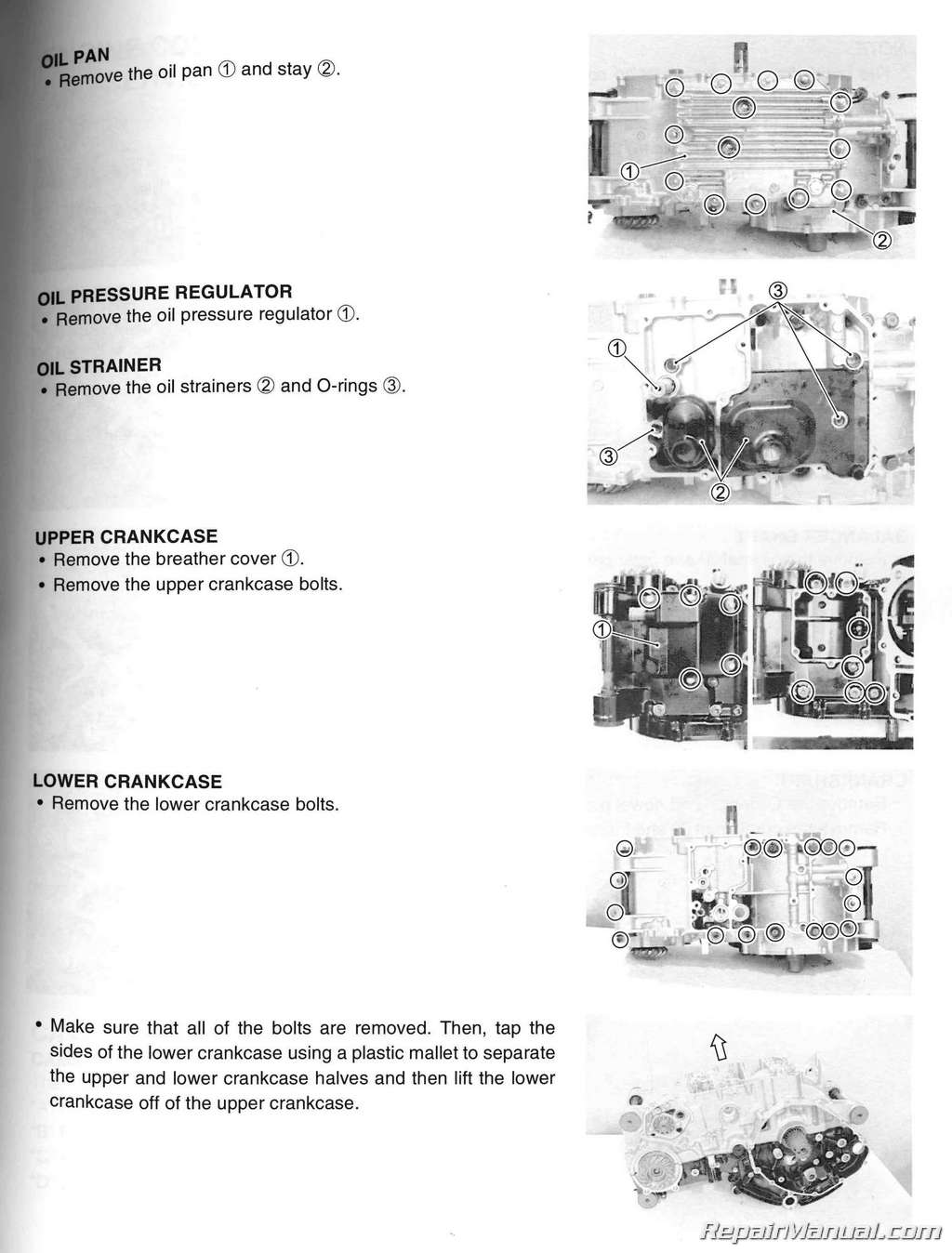
Crankcase
Balancer Driven Gear
Crankshaft And Conrod
Crankshaft Journal Bearing
Crankshaft Thrust Bearing
Engine Reassembly
Chapter 4: Driveline/Axle
Secondary Bevel Gears
Construction
Removal
Disassembly
Inspection
Reassembly
Secondary Gear Shims Adjustment
Final Bevel Gears
Construction
Final Gear Case Removal
Final Gear Case Disassembly
Final Gear Shims Adjustment
Final Gear Case Reassembly
Final Gear Case Installation
Chapter 5: FI System Diagnosis
Precautions In Servicing
Electrical Parts
Fuse
Ecm/va Rio Us Sensors
Electrical Circuit Inspection Procedure
Using The Multi-circuit Tester
Fi System Technical Features
Injection Time (injection Volume)
Compensa Tion Of Injection Time (volume)
Injection Stop Control
Fi System Parts Location
Fi System Wiring Diagram
Ecm Terminal
Self-diagnosis Function
User Mode
Dealer Mode
Tps Adjustment
Fail-safe Function
Fi System Troubleshooting
Customer Complaint Analysis
Visual Inspection
Self-diagnostic Procedures
Self-diagnosis Reset Procedure
Use Of Sds Diagnostic Procedures
Use Of Sds Diagnosis Reset Procedure
Show Data When Trouble
(displaing Data At The Time Of Dtc)
Malfunction Code And Defective Condition
“c12” (p0335) Ckp Sensor Circuit Malfunction
“c13” (p1750-h/l) Or “c17’’ (p0105-h/l) Iap Sensor
Circuit Malfunction
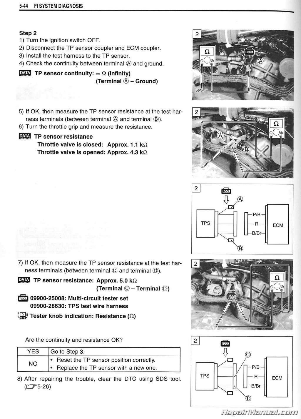
“cl4” (p0120-h/l) Tp Sensor Circuit Malfunction
“c15’’ (p0115-h/l) Ect Sensor Circuit Malfunction
“c21” (p0110-h/l) Ia T Sensor Circuit Malfunction
“c23” (p1651-h/l) To Sensor Circuit Malfunction
“c24” (p0351), “c25” (p0352), “c26” (p0353) Or
“c27” (p0354) Ignition System Malfunction
“c28” (p1655) Stv Actuator Circuit Malfunction
“c29” (p1654-h/l) Stp Sensor Circuit Malfunction
“c31” (p0705) Gp Switch Circuit Malfunction
“c32” (p0201) Or “c33” (p0202) Fuel Injector Circuit
Malfunction
“c40” (p0505-h/l Or P0506 And P0507) Isc Valve Circuit
Malfunction
“c41 ” (p0230-h/l) Fp Rela Y Circuit Malfunction
“c42” (p01650) Ig Switch Circuit Malfunction
“c44” (p0156/p0161) Or “c64” (p0130/p0135) H02
Sensor (h02s) Circuit Malfunction (for E-02, 19, 24)
“c46” (p1657-h/l Or P1658) Excv Actuator Circuit
Malfunction
“c49” (p1768) Or “c61” (p1656) Pair Control
Solenoid Valve Circuit Malfunction
“c60” (p0480) Cooling Fan Relay Circuit Malfunction
Sensors
Iap Sensor Inspection
Iap Sensor Removal And Installation
Tp Sensor Inspection
Tp Sensor Removal And Installation
Tps Adjustment
Stp Sensor Inspection
Stp Sensor Removal And Installation
Stp Sensor Adjustment
Ckp Sensor Inspection
Ckp Sensor Removal And Installation
I A T Sensor Inspection
I At Sensor Removal And Installation
Ect Sensor Inspection
Ect Sensor Removal And Installation
To Sensor Inspection
To Sensor Removal And Installation
H02 Sensor Inspection (for E-02, 19, 24)
H02 Sensor Removal And Installation
(for E-02, 19, 24)
Chapter 6: Fuel System and Throttle Body
Fuel Delivery System
Fuel System
Fuel Tank Removal
Fuel Tank Inst Alla Tion
Fuel Pressure Inspection
Fuel Pump Inspection
Fuel Discharge Amount Inspection
Fuel Pump Rela Y Inspection
Fuel Pump And Fuel Level Gauge Removal
Fuel Level Gauge Inspection
Fuel Pump Disassembly
Fuel Mesh Filter Inspection
Fuel Pump And Fuel Level Gauge Reassembly And
Installation
Throttle Body
Construction
Air Cleaner Box Removal
Air Cleaner Box Installation
Air Cleaner Chamber And Throttle Body Removal
Throttle Body Disassembl Y
Throttle Body Cleaning
Inspection
Isc Valve Inspection
Isc Val Ve Removal
Inspection
Isc Valve Installation
Throttle Body Reassembly
Air Cleaner Chamber And Throttle Body Installation
Stp Sensor Adjustment
Fuel Injector Removal
Fuel Injector Inspection
Fuel Injector Installation
Throttle Valve Synchronization
Throttle Position Sensor (tps) Setting
Chapter 7: Exhaust System
Excva (exhaust Control Valve Actuator)
And Excv (exhaust Control Valve)
Excva And Excv Removal
Excva Inspection
Excv Inspection
Cable Inspection
Excva And Excv Installation
Excva Adjustment
Exhaust Pipe And Muffler
Removal
Installation
Chapter8: Cooling and Lubrication System
Engine Coolant
Cooling Circuit
Cooling Circuit Inspection
Radiator And Water Hose
Radiator Removal And Disassembly
Radi A Tor Disassembl Y
Radiator Cap Inspection
Radiator Inspection And Cleaning
Radiator Reassembly
Radiator Installation
Water Hose Inspection
Cooling Fan
Inspection
Cooling Fan Relay Inspection
Ectsensor
Removal
Inspection
Installation
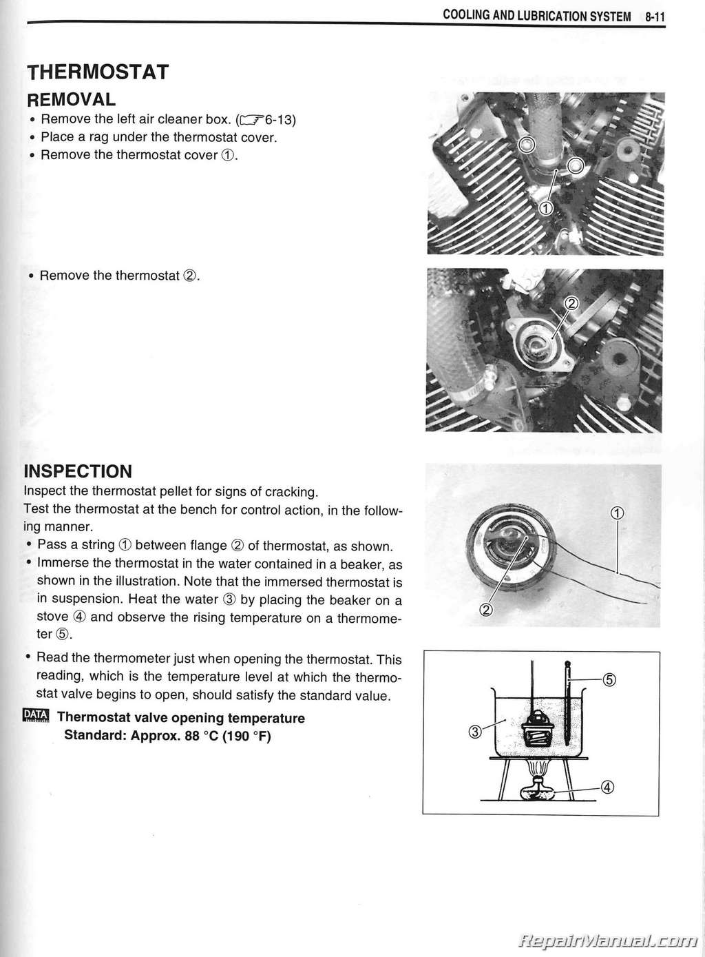
Thermostat
Removal
Inspection
Installation
Water Pump
Removal And Disassembly
Inspection
Reassembly And Installation
Engine Lubrication System Chart
Chapter 9: Chassis
Exterior Parts
Fastener Removal And Installation
Front And Rear Seat
Frame Side Cover
Rear Frame Cover
Frame Head Cover And Radiator Cover
Front Wheel
Construction
Removal
Inspection And Disassembl Y
Reassembl Y And Inst Alla Tion
Front Fork
Construction
Removal And Disassembly
Inspection
Reassembly
Installation
Steering
Construction
Removal
Inspection And Disassembl Y
Reassembly
Installation
Steering Tension Adjustment
Handlebars
Construction
Removal
Installation
Rear Wheel
Construction
Removal
Disassembly
Inspection And Disassembl Y
Reassembly And Installation
Rear Suspension
Construction
Removal
Inspection And Disassembl Y
Rear Shock Absorber Disposal
Reassembly
Installation
Suspension Setting
Front Brake
Construction
Brake Pad Replacement
Brake Fluid Replacement
Caliper Removal
Caliper Disassembly
Caliper Inspection
Caliper Reassembly
Caliper Installation
Brake Disc Inspection
Master Cylinder Removal And Disassembly
Master Cylinder Inspection
Master Cylinder Reassembly
Master Cylinder Installation
Rear Brake
Construction
Brake Pad Replacement
Brake Fluid Replacement
Caliper Removal
Caliper Disassembly
Caliper Inspection
Caliper Reassembly
Caliper Installation
Master Cylinder Removal
Master Cylinder Disassembly
Master Cylinder Inspection
Master Cylinder Reassembly
Master Cylinder Installation
Tire And Wheel
Tire Removal
Inspection
Valve Inspection
Tire Installation
Balancer Weight Installation
Chapter 10: Electrical System
Cautions In Servicing
Connector
Coupler
Clamp
Fuse
Semi-conductor Equipped Part
Battery
Connecting The Battery
Wiring Procedure
Using The Multi-circuit Tester
Location Of Electrical Components
Charging System
Troubleshooting
Inspection
Starter System And Side-stand/
Ignition Interlock System
Chapter 11: Servicing Information
Troubleshooting
Starter Motor Removal
Starter Motor Disassembly
Starter Motor Inspection
Starter Motor Reassembly
Starter Relay Inspection
Side Stand/ignition Interlock System Parts
Inspection
Ignition System
Troubleshooting
Inspection
Speedometer And Tachometer
Description
Speedometer Removal And Disassembly
Tachometer Removal And Disassembly
Inspection
Troubleshooting
Fi System Malfunction Code And
Defective Condition
Engine
Radiator (cooling System)
Chassis
Shaft Drive
Brakes
Electrical
Battery
Special Tools
Tightening Torque
Engine
Driveline/axle
Fi System And Intake Air System
Cooling System
Chassis
Tightening Torque Chart
Service Data
Wiring Harness, Cable And Hose Routing
Wiring Harness Routing
Engine Electrical Parts Lead Wire Routing
Cable Routing
Front Brake Hose Routing
Rear Brake Hose Routing
Throttle Body Hose Routing
Cooling System Hose Routing
Pair (air Supply) System Hose Routing
(for E-03, 28, 33)
Pair (air Supply) System Hose Routing
(for The Others)
Fuel Tank Installation
Frame Head Cover And Radiator Cover
Installation
Frame Head Cover Cushion Installation
Radiator Upper Cover Cushion Installation
Left Frame Covers Installation
Right Frame Covers Installation
Headlight Cover Installation
Ignition Coil Installation
Side-stand Installation
Rear Turn Signal Light, License Light Wire Routing
Seat Lock Cable Routing
License Light And License Plate Installation
Brake Light/taillight Installation
Chapter 12: Emission Control Information
Emission Control Systems
Fuel Injection System
Crankcase Emission Control System
Exhaust Emission Control System (pair System)
Noise Emission Control System
Evaporative Emission Control System (only For E-33) Pair (air Supply) System And Emission Control System
Inspection
Pair Hoses
Pair Reed Valve
Pair Control Solenoid Valve
Pair (air Supply) System Hose Routing (for E-03, 28, 33)
Pair (air Supply) System Hose Routing (for The Others) Heated Oxygen Sensor (h02s) Inspection (for E-02, 19, 24) Evaporative Emission Control System Inspection (only For E-33)
Hoses (evap Hose)
Evap Canister
Evap Canister Hose Routing (only For E-33)

 SKU: U99500-42080-01E
 SKU: U99011-02B73-03A
 SKU: U99011-02B83-03A
