Description
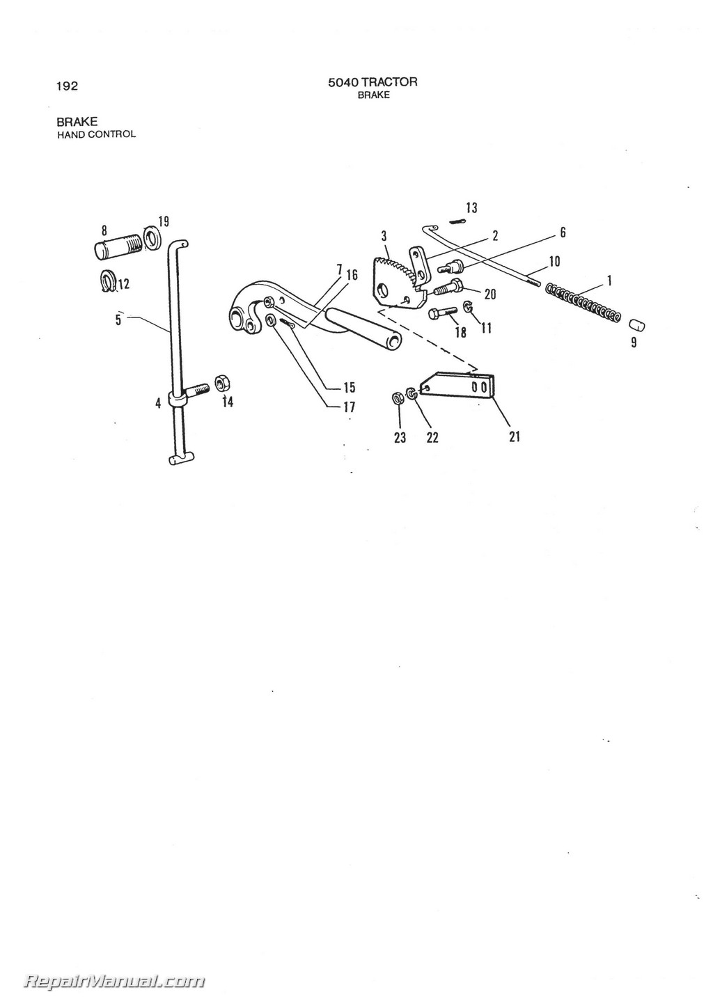
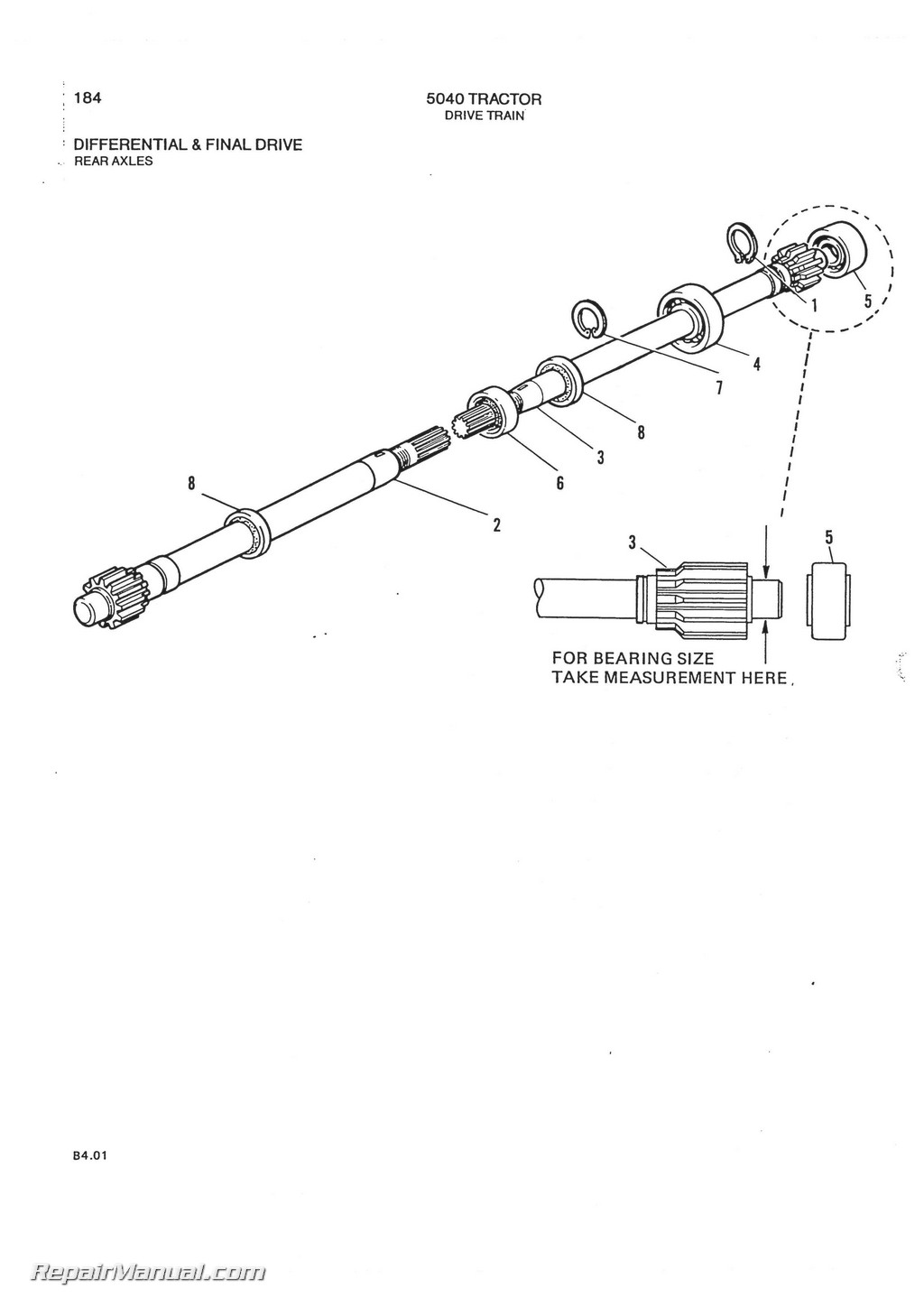
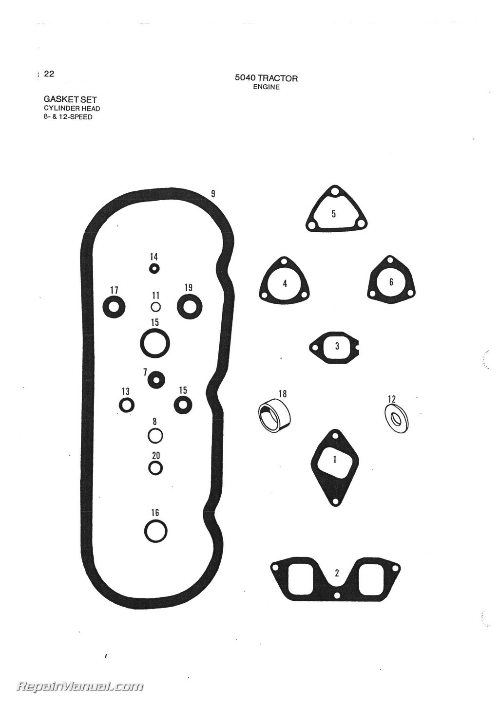
This 243 page, Allis Chalmers 5040 Parts Manual includes detailed illustrated and part numbers for every part of the Allis Chalmer 5040 tractor. Includes parts information for 6 speed, 8 speed, 9 speed and 12 speed transmissions. Please note this publication is out of print and available as a reproduction only.
Table of Contents
AIR INTAKE & EXHAUST SYSTEM
Air Cleaner
I ndicator, Restriction
Manifold
Intake & Exhaust
Muffler
AXLE, STEERING & WHEELS Axle
Front
Rear
Spindle
Steering
Control
Cylinder
Linkage
Tie Rod
Wheel
Front
Rear
Power Adjust
Standard
Weight
BRAKE
Brake, Hand Control
Brake, Locking
Pedal & Foot Control
COOLING SYSTEM
Belt, Fan
Fan & Fan Drive
Lines
Pump, Water
Radiator
Thermostat
DRIVE TRAIN Axle & Final Drive Axle, Shaft
Rear
Gears, Final Drive
Rear
Housing & Final Drive
Rear
Clutch
Luk
Luk
Luk
OMG
Controls
Clutch, Foot Release
Clutch, Hand Release
Differential Lock
Differential
Gears
Rear
Housing
Rear
Lock
GearShift
PTO
Shafts & Gears
Shifter
Range Selector
Transmission
Cover
Gears
Housing
Input Shaft
Reduction Gears
Shift Fork & Rails
Range Selector
Transmission
ELECTRICAL & INSTRUMENTS
Electrical Lighting
Flasher Lamps
Flood Lamp
Head Lamps
Tail Lamp
Warning Lamp
Wiring
Work Lamp
Engine Electrical System Alternator
Drive
Electronic Type — Niehoff
Mechanical Type
Battery
Starting Motor
Bosch
Fiat
Lucas
Marelli
Wiring
Harness
Instruments
Gauges
Remote Electric Socket
Switch
ignition
Wiring
ENGINE
Camshaft
Connecting Rod & Bearings
Crankshaft & Bearings
Cylinder Block
Cylinder Head
Cylinder Sleeve
Flywheel
Gasket Set
Cylinder Head
Intermediate
Major Overhaul
Lubricating System
Oil Filter
Oil Pan
Oil Pump
Manifold
Piston
Push Rods
Rocker Arms
Timing Gear
Cover
Valve, Intake & Exhaust
Spring
FUEL SYSTEM Controls
Foot Throttle
Fuel Shut-off
Hand Throttle
Filters, Primary & Secondary
Lines
Fuel Injection System
Drive
Fuel Injector
CAV
Fiat
OMAP
Lines
Self-Injection
Starting Aid
Pump
Governor
Retard & Damper
Rotor
Tank
Lines
HITCH & LIFT Controls
Drawbar
Lift Shaft
Arms
Cylinder
Housing
Top Link Sensing
3-Point Hitch
Lift Link
Upper & Lower
HYDRAULIC SYSTEM Controls
Inner
Outer
Cylinder
Power Steering
Filter
Lift System
Lines
Lift System
Power Steering
W/O Reservoir Tank
W/ReservoirTank
Remote
Pump
Lift System
Drive
Power Steering
W/O Reservoir Tank
W/ReservoirTank
Tank
Valve
Control Lift
Remote Cylinder
NUMERICAL INDEX
RECOMMENDED DEALER STOCK
SERIAL NUMBER LOCATION
SHEET METAL, FRAME & SEAT Frame
Protective
Seat
Sheet Metal & Frame
BatterySupport
Decals
Fenders
Flat Shape & Platform
Curved Shape & Platform
Grille
Hood
Instrument Panel
ALPHABETICAL INDEX
The complete alphabetical index appears at the beginning of this publication. It is used to locate major groups, assemblies and components.
NUMERICAL INDEX
The numerical index of this publication follows the Alphabetical Index at the beginning of the publication and indicates at which grid location and page number a part number appears.
ILLUSTRATIONS
All illustrations are located on the left hand page with the text on the right. Except for some common hardware, all parts are identified with an item number which corresponds to the “item” column on the text page. This is followed by the part number, quantity and description.
HARDWARE
Common hardware not identified such as bolts, nuts, cotter pins and lube fittings, are listed indented in the text beneath the item to which they attach or fit. Common hardware listed indented beneath an item is NOT included unless specified. Example: (Incl. BOLT. LOCKWASHER AND NUT).
ORDERING PARTS
Be sure to refer to both the text and the illustration to assure ordering the correct part.
RECOMMENDED DEALER STOCK
A recommended dealer stock listing appears at the end of this publication.

