Description
This 2009 – 2013 Honda MUV700 Big Red Service Manual provides service, repair, and maintenance for 2009-2013 Honda MUV700 Big Red UTVs. This is the same manual your local Honda dealer uses so you’ll have all the information you need to service your own Honda Big Red. This manual is printed and bound by Honda and is an official OEM printed manual.
Honda MUV700 Big Red Service Manual Model Coverage
2009 Honda MUV700 Big Red
2010 Honda MUV700 Big Red
2011 Honda MUV700 Big Red
2012 Honda MUV700 Big Red
2013 Honda MUV700 Big Red
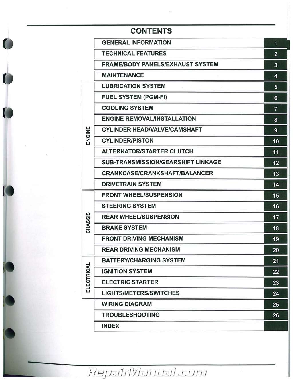
Table of Contents
General Information
Technical Features
Frame/body Panels/exhaust System
Maintenance
Lubrication System
Fuel System (pgm-fi)
Cooling System
Engine Removal/installation
Cylinder Head Valve/camshaft
Cylinder/piston
Alternator/starter Clutch
Sub-transmission/gearshift Linkage
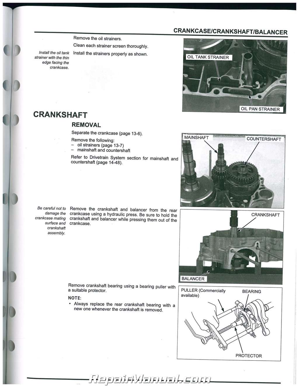
Crankcase/crankshaft/balancer
Drivetrain System
Front Wheel/suspension
Steering System
Rear Wheel/suspension
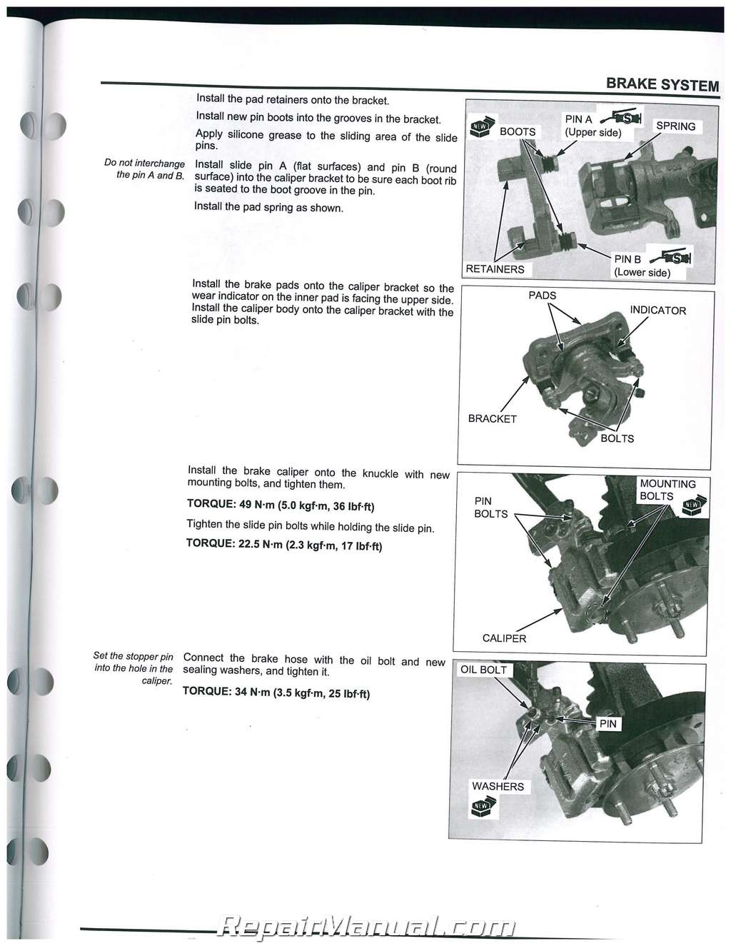
Brake System
Front Driving Mechanism
Rear Driving Mechanism
Battery/charging System
Ignition System
Electric Starter
Lights/meters/switches
Wiring Diagram
Troubleshooting
Index
Index of Topics
Accelerator Pedal
Accessory Socket
Air Cleaner
Air Cleaner Housing
Air Cleaner Housing Drain Tube
Alternator Charging Coil
Alternator Stator/starter Reduction
Gears
Battery
Battery/charging System
Maintenance
Body Panel Locations
Brake Fluid
Brake Fluid Replacement/air Bleeding
Brake Inhibitor Relay
Brake Pad/disc
Brake Pads Wear
Brake Pedal
Brake System
Brake/taillight
Cable & Harness Routing
Camshaft
Cargo Bed
Center Frame Cover
Charging System Inspection
Chassis Lubrication Points
Combination Meter (after ’09 Canada)
Component Location
Battery/charging System
Drivetrain System
Electric Starter
Ignition System
Lights/meters/switches
Pgm-fi System
Coolant Replacement
Cooling Fan
Cooling Fan Motor
Cooling System
Cooling System Flow Pattern
Cooling System Testing
Crankcase Assembly
Crankcase Bearing Replacement
Crankcase Separation
Crankshaft
Crossbar
Cylinder Compression
Cylinder Head Assembly
Cylinder Head Cover Assembly/
Installation
Cylinder Head Cover Removal/
Disassembly
Cylinder Head Disassembly
Cylinder Head Inspection
Cylinder Head Installation
Cylinder Head Removal
Cylinder/piston Inspection
Cylinder/piston Installation
Cylinder/piston Removal
Differential Oil
Diode
Door
Drive Mode Selector Cable Adjustment
Drive Mode Selector Lever Linkage
Drive Shaft Boots
Drivetrain Connector Location
Drivetrain Dtc Index
Drivetrain Dtc Troubleshooting
Drivetrain System Diagram
Drivetrain Troubleshooting
Information
Dtc Troubleshooting
Ect sensor
Emission Control Systems
Engine Front Cover (’09 – ’10 Model)
Engine Idle Speed
Engine Installation
Engine Oil
Engine Removal
Engine Temperature Indicator
Eot Sensor
Exhaust System
Frame/body Panels/exhaust System
Maintenance
Floor Cross Plate
Floor Panel
Flywheel/starter Clutch
Foot Brake Switch
Lights/meters/switches
Maintenance
Footrest Panel
Front Brake Caliper
Front Bumper
Front Crankcase Cover
Front Differential Lock Clutch
Front Drive Shaft
Front Final Clutch
Front Final Drive Installation
Front Final Drive Removal
Front Final Gear Assembly
Front Final Gear Case Bearing
Replacement
Front Final Gear Disassembly/
Inspection
Front Grille
Front Hood
Front Propeller Shaft
Front Shock Absorber
Front Suspension Arm
Front Wheel
Front Wheel Hub And Knuckle
Fuel Injector
Fuel Line
Fuel Line Inspection
Fuel Pump
Fuel Tank
Fuel Tank Plate/cover
Gear Position Switch
Gear Selector Cable Adjustment
Gear Selector Lever Linkage
Headlight
Iacv
Ignition Coil
Ignition Switch
Ignition System Inspection
Ignition Timing
Indicators
Instrument Panel
Intake Air Duct
Lift And Support Points
Lighting/dimmer Switch
Low Fuel Indicator
Lubrication & Seal Points
Lubrication System Diagram
Main Relay/fuel Pump Relay
Maintenance Lid
Maintenance Schedule
Master Cylinder
Mil Circuit Inspection
Model Identification
Mudguard
Occupant Protective Structure (ops)
Oil Cooler
Oil Pressure Check
Drive! Rain System
Lubrication System
Oil Pump
Parking Brake Cable Plate (after ’10)
Parking Brake Lever
Parking Brake Lever Bracket
Parking Brake Switch
Pcm
Pgm-fi Connector Location
Pgm-fi Dtc Index
Pgm-fi System Diagram
Pgm-fi Troubleshooting Information
Radiator
Radiator Reserve Tank
Rear Brake Caliper
Rear Crankcase Cover
Rear Differential Lock Clutch
Rear Drive Shaft
Rear Final Drive Installation
Rear Final Drive Removal
Rear Final Gear Assembly
Rear Final Gear Case Bearing
Replacement
Rear Final Gear Disassembly/
Inspection
Rear Shock Absorber
Rear Suspension Arm
Rear Wheel
Rear Wheel Hub/knuckle
Regulator/rectifier
Seat
Seat Belt
Seat Center Cover
Seat Under Cover
Service Information
Alternator/starter Clutch
Battery/charging System
Brake System
Cooling System
Crankcase/crankshaft/balancer
Cylinder Heada/alve/camshaft
Cylinder/piston
Drivetrain System
Electric Starter
Engine Removal/installation
Frame/body Panels/exhaust System
Front Driving Mechanism
Front Wheel/suspension
Fuel System (pgm-fi)
Ignition System
Lights/meters/switches
Lubrication System
Maintenance
Rear Driving Mechanism
Rear Wheel/suspension
Steering System
Sub-transmission/gearshift Linkage
3ervice Rules
Shift Clutch/mainshaft/countershaft
Shift Valve Body
Side Net
Frame/body Panels/exhaust System
Side Net (after’10)
Maintenance
Side Panel
Spark Arrester
Spark Plug
Specifications
Alternator/starter Clutch
Battery/charging System
Brake System
Cooling System
Crankcase/crankshaft/balancer
Cylinder Head Valve/camshaft
Cylinder/piston
Drivetrain System
Electric Starter
Front Driving Mechanism
Front Wheel/suspension
Fuel System
General
Ignition System
Lights/meters/switches
Lubrication System
Rear Driving Mechanism
Rear Wheel/suspension
Steering System
Sub-transmission/gearshift Linkage
Starter Motor
Starter Relay Switch:
Steering Column And Shaft
Steering Gear Box
Steering System
Steering Wheel
Sub-transmission
Suspension
Symptom Troubleshooting
Drivetrain System
Fuel System (pgm-fi)
System Components
Alternator/starter Clutch
Brake System
Crankcase/crankshaft/balancer
Cylinder Heada/alve/camshaft
Cylinder/piston
Drivetrain System
Engine Removal/installation
Front Driving Mechanism
Front Wheel/suspension
Fuel System (pgm-fi)
Rear Driving Mechanism
Rear Wheel/suspension
Steering System
Sub-transmission/gearshift Linkage
System Diagram
Battery/charging System
Electric Starter
Ignition System
Technical Features
Automatic Transmission System
Pgm-fi System
Recreational Utility Vehicle Overview • Selectable 4wd And Differential Lock
System
Thermostat
Throttle Body
Throttle Operation
Tie-rod And Joint Boot
Tie-rod Ball Joint
Tires
Torque Converter
Torque Values
Engine & Frame
Standard
Tp Sensor/map Sensor (sensor Unit)
Troubleshooting
Alternator/starter Clutch
Battery/charging System
Brake System
Cooling System
Crankcase/crankshaft/balancer
Cylinder Head Valve/camshaft
Cylinder/piston
Electric Starter
Engine Does Not Start Or Is Hard To
Start
Engine Lacks Power
Frame/body Panels/exhaust System
Front Driving Mechanism
Front Wheel/suspension
Ignition System
Lubrication System
Poor Performance At High Speed
Poor Performance At Low And Idle
Speed
Rear Driving Mechanism
Rear Wheel/suspension
Steering System
Sub-transmission/gearshift Linkage –
Underbody
Valve Clearance
Valve Guide Replacement
Valve Seat Inspection/refacing
Vs Sensor
Water Pump
Wheels/tires
Wiring Diagram

 SKU: ATV2-1
 SKU: M315
 SKU: M505
