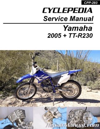
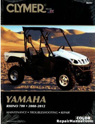
Description
This 1977 Yamaha XS750D XS7502D Service Manual provides detailed service information, step-by-step repair instruction and maintenance specifications for the 1977 Yamaha XS750D and 1977 Yamaha XS7502D motorcycles. Please note this book is a reproduction of the original out of print manual and not an original first printing.
Table of Contents
CHAPTER 1. GENERAL INFORMATION
Machine identification
Special tools.
CHAPTER 2.
PERIODIC INSPECTION AND ADJUSTMENT
Introduction
Maintenance Interval Charts.
A. Maintenance Intervals for New Machines,
B. Routine Maintenance Intervals.
C. Lubrication Intervals for New Machines
D. Routine Lubrication Intervals.
E. Recommended Lubricants.
Engine
A. Carburetor
B. Air Filter.
C. Engine/Transmission Oil
D. Middle Gear/Final Gear Oil.
E. Clutch Adjustment
F. Cam Chain Adjustment.
G. Valve Clearance Adjustment.
H. Compression Pressure Measurement.
Chassis.
A. Fuel Petcock Cleaning.
B. Fuel Petcock Disassembly
C. Front and Rear Brake.
D. Wheels and Tires.
E. Front Fork Oil Change.
F. Steering Head Adjustment
G. Throttle Cable with Grip Lubrication
H. Lubrication of Levers, Pedals, etc
Electrical.
A. Contact Breaker Point Adjustment
B. Contact Breaker Point Maintenance.
C. Ignition Timing.
D. Battery.
E. Spark Plug
F. Headlight.
CHAPTER 3. ENGINE OVERHAUL
Engine Removal
.A. Preparation for Removal.
B. Fuel Tank Removal
C. Muffler, Footrest, Brake Pedal.
D. Side Cover, Air Cleaner Case.
E. Wiring and Cables.
F. Drive Shaft Joint.
Engine Disassembly
A. Cylinder Head and Cylinder Removal
B. Cylinder Head Disassembly
C. Piston Removal.
D. Generator
E. Bearing Housing
F. Clutch and Primary Driven Gear.
G. Kick Gear Removal
H. Shift Lever, Shift Shaft Removal.
I. Governor Assembly Removal
J. Electric Starter Removal.
K. Middle Gear Removal
L. Transmission Bearing Housing Removal,
M. Breather Removal.
N. Oil Pump Removal and Disassembly.
0. Crankcase Disassembly
P. Transmission Disassembly.
Q. Transmission Illustration
R. Shift Cam Illustration.
Inspection and Repair.
A. Cylinder Head Cover
B. Cylinder Head
C. Vaive, Valve Guide and Valve Seat
D. Valve Spring and Lifters.
E. Camshafts, Cam Chain and Cam Sprockets.
F. Cylinder.
G. Piston and Piston Rings
H. Piston Pin.
I. Crankshaft.
J. Connecting Rod.
K. Oil Pump
L. Primary Drive.
M. Transmission
N. Starter Drives
0. Crankcases and Strainer Cover
P. Bearings and Oil Seals
Q. Middle Gear Case
Engine Assembly and Adjustment,
A. Shift Cam.
B. Transmission
C. Crankshaft and Crankcases.
D. Oil Pump
E. Shifter Assembly
F. Kick Starter Assembly.
G. Clutch and Primary Drive
H. Bearing Housing.
1. Right Crankcase Cover.
J. Middle Gear.
K. Drive Axle Bearing Housing.,
L. Left Crankcase Cover
M. Ignition Assembly.
N. Pistons and Cylinder
0. Cylinder Head Installation
P. Camshaft Installation.
Q. Cam Chain Installation
R. Cylinder Head Cover.
Remounting Engine
A. Remounting Engine
CHAPTER 4. CARBURETOR
Carburetor
A. Description
B. Specifications
C. Disassembly.
D. Inspection.
E. Adjustments
CHAPTER 5. CHASSIS
Front Wheel
A. Removal.
B. Front Axle Inspection.
C. Front Wheel Inspection
D. Replacing Wheeel Bearings.
E. Installing Front Wheel
Rear Wheel.
A. Removal.
B. Rear Axle Inspection
C. Replacing Wheel Bearings
D. Rear Wheel Inspection.
E. Installing Rear Wheel.
Brakes.
A. Caliper Pad Replacement.
B. Caliper Disassembly (Front and Rear),
C. Master Cylinder Disassembly.
D. Brake Inspection and Repair.
E. Brake Reassembly
Wheels, Tires, Tubes.
A. Wheel Inspection
B. Tire, Tube Removal
C. Installation
Front Forks
A. Removal and Disassembly.
B. Inspection
C. Assembly,.
Steering Head.
A. Adjustment
B. Removal.
C. Inspection
D. Reassembly
Swing Arm.
A. Inspection
B. Adjustment
C. Removal.
D. Inspection and Lubrication
E. Installation
Rear Shock Absorber
A. Removal
B. Inspection!
Cables and Fittings.
A. Cable Maintenance
B. Throttle Maintenance
Final Drive Gear
CHAPTER 6. ELECTRICAL
Electric Starting System.
A. Starter Motor.
B. Starter Relay Switch
Charging System
A. Charging Circuit Diagram
B. A. C. Generator.
C. Voltage Regulator.
D. Checking Silicon Rectifier
E. Battery.
Ignition System
A. Ignition Circuit Diagram
B. Governor Assembly.
C. Spark Gap Test
D. Ignition Coil.
E. Condenser Test
Spark Plug.
A. How To “Read” a Spark Plug
B. Inspection
Lighting and Signal Systems
A. Lighting Tests
B. Reserve Lighting System.
C. Self-Canceling Flasher System.
D. XS750-2D 1C Voltage Regulator-Rectifier
General Wiring Circuit Diagram
APPENDICES
Specifications.
A. General Specifications
B. Maintenance Specifications
C. Torque Specifications.
D. Valve Timing
Conversion Tables .
Consumer Information.
Electrical Circuit Diagram
Lubrication Diagram .
Technical Bulletins


 SKU: CPP-293
 SKU: M281-4
 SKU: M291

