Description
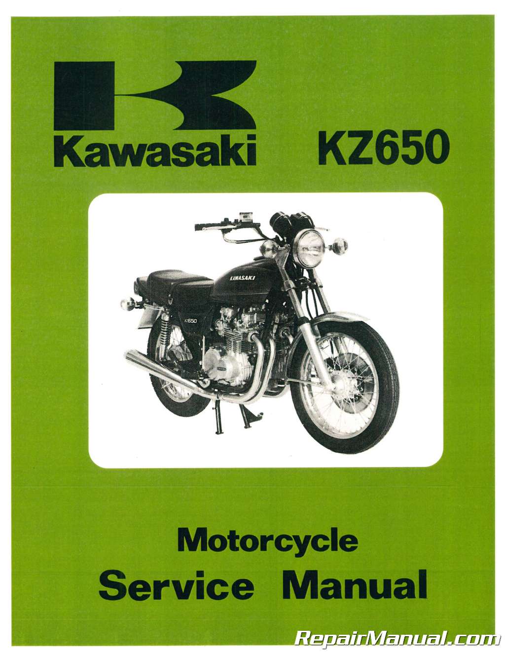
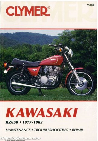
This 320 page, 1978 – 1980 Kawasaki KZ650 Repair Manual is a reproduction of the original out of print manual. This book includes service and repair information for 1978 – 1980 Kawasaki KZ650 motorcycles.
Motorcycle Coverage
1980 Kawasaki KZ650F1 (UK)
1980 Kawasaki KZ650E1 LTD
1980 Kawasaki KZ650D3
1980 Kawasaki KZ650C4
1980 Kawasaki KZ650B4
1979 Kawasaki KZ650D2 SR Series
1979 Kawasaki KZ650C3 Custom
1979 Kawasaki KZ650B3
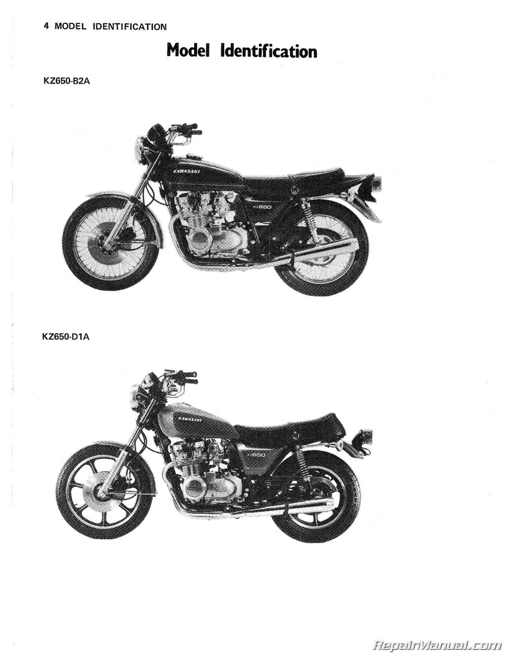
1978 Kawasaki KZ650 D1A
1978 Kawasaki KZ650 B2A
Index of Topics
Additional Consideration for Racing
Alternator (Dynamo)
Air Cleaner
Air Injection System
Air Suction Valve
Armature (Stator)
Axle
Ball Bearings
Battery
Bearings
Engine
Wheel
Brakes
Disc
Drum
Front
Rear
Drum
Disc
Brake Light Circuit
Brake Light Switch
Front
Rear
Breather (Oil)
Bypass Valve
Cables
Clutch
Speedometer
Tachometer
Throttle
Caliper
Front
Rear
Camshaft
Camshaft Chain
Camshaft Chain Guides
Roller (Lower)
Sprocket (Front)
Sprocket (Upper)
Tensioner
Camshaft Chain Tensioner
Camshaft Sprocket
Capacitor
Carburetor
Carburetor Holder
Chains
Camshaft
Drive
Drum Brake
Disc Brake
Primary
Charging System
Circuits
Brake Light
Hazard
Headlight
Starter Motor
Turn Signal
Clutch
Clutch Cable
Clutch Release
Connecting Rod
Contact Breaker
Crankcase Split
Crankshaft
Cylinder Block
Cylinder Head
Cylinder Head Cover
Disc Brake
Front
Rear
Drive Chain
Drum Brake
Disc Brake
Drive Shaft
Dynamo (Alternator)
Armature (Stator)
Flywheel (Rotor)
Electric Starter System
Engine Lubrication
Engine Oil
Engine Oil Pump
Engine Performance Curves
Engine Perspective
Engine Removal
Engine Sprocket
Engine Sprocket Cover
External Shift Mechanism
Flow Charts
Disassembly—Chassis
Rear Drum Brake
Rear Disc Brake
Disassembly—Engine Installed
Disassembly—Engine Removed
Engine Removal
Flywheel (Rotor)
Front Brake
Front Brake Light Switch
Front Caliper
Front Fork
Front Hub
Single Disc Brake
Dual Disc Brake
Front Wheel
Single Disc Brake
Dual Disc Brake
Fuel System
Fuel Tank
Fuel Tap
General Lubrication
Grease Seals
Handlebar
Hazard Circuit
Headlight
Headlight Circuit
Horn
Hub
Front
Single Disc Brake
Dual Disc Brake
Rear
Drum Brake
Disc Brake
Ignition Coil
Ignition Switch
Ignition System
Ignition Timing
Indicator Light
Introduction to Disassembly
Kickstarter
Kickstarter Spring
Lighting System
Lights
Headlight
Indicator
Meter
Tail/Brake
Turn Signal
Locking Agent
Low Fuel Warning System
Lubrication
Engine
General
Master Cylinder
Front
Rear
Meter Light
Model Identification
Mufflers
KZ650-B, C, F
KZ650-D, E
Needle Bearing
Nuetral Switch
Oil Breather
Oil Filter
Oil Filter Bypass Valve
Oil Pressure Relief Valve
Oil Pressure Switch
Oil Pump (Engine)
Oil Seal
Output Shaft
Pads
Front
Rear
Performance Curves
Engine
Running
Periodic Maintenance Chart
Piston
Piston Ring
Point Gap Adjustment
Primary Chain
Rear Brake
Drum
Disc
Rear Brake Light Switch
Rear Caliper
Rear Hub
Drum Brake
Disc Brake
Rear Shock Absorbers
Rear Sprocket
Rear Wheel
Drum Brake
Disc Brake
Rear Wheel Coupling
Drum Brake
Disc Brake
Rectifier
Regulator
Relief Valve
Rim
Rotor (Flywheel)
Running Performance Curves
Secondary Shaft
Shafts
Camshaft
Crankshaft
Drive
Output
Secondary
Shift Drum
Spark Plug
Special Tool
Specifications
Speedometer
Speedometer Cable
Speedometer Light
Speedometer Gear Housing
Spoke
Sprockets
Camshaft
Camshaft Chain Guide
Engine
Rear
Starter Motor
Starter Motor Circuit
Starter Motor Clutch
Starter Motor Idle Gear
Stator (Armature)
Steering
Steering Stem
Steering Stem Bearing
Swing Arm
Switches
Front Brake Light
Ignition
Neutral
Oil Pressure
Rear Brake Light
Tachometer
Tachometer Cable
Tachometer Light
Tail/Brake Light
Throttle Cables
Timing Advancer
Tires
Torque and Locking Agent
Transmission
Troubleshooting Guide
Tube
Turn Signal Assembly
Turn Signal Circuit
Turn Signal Light
Valves
Valve Adjustment Chart
Valve Clearance
Valve Guide
Wheels
Front
Single Disc Brake
Dual Disc Brake
Rear
Drum Brake
Disc Brake
Wheel Balance
Cast Wheel
Wire-Spoke Wheel
Wheel Bearing
Wheel Coupling
Drum Brake
Disc Brake
Wiring Diagram
KZ650-B2A
KZ650-B3
KZ650-B4
KZ650-C3
KZ650-C4
KZ650-D1A
KZ650-D2
KZ650-D3
KZ650-E1
KZ650-F1
The following excerpt is an example of the content found in the electrical chapter of this 1978-1980 Kawasaki KZ650 Motorcycle Service Repair Manual.
A wiring diagram of one half of the KZ650 ignition system is shown in Fig. K12. The other half is identical, and works as follows. The KZ650 battery supplies the current for the primary circuit, which includes the contact breaker points, capacitor, and the primary winding of the ignition coil. When the points suddenly open with the ignition switch turned on, a surge of electrons is produced in the secondary circuit, which includes the ignition coil secondary winding and the two spark plugs. The two sets of points and two coils take the place of a distributor, which is left out to increase the reliability of the system. Each set of points fires two spark plugs every time the two pistons rise, that is, once every 360° of crankshaft rotation. Since the two sets of points (and the two sets of pistons) are 180° out of phase, plugs 2 and 3 fire 180° of crankshaft rotation after plugs 1 and 4 fire, and vice versa. For this system to function properly, all ignition parts must be in good order, the ignition timing correctly set, the ignition and engine stop switches not shorted, and all wiring in good condition (no shorts or breaks, and no loose or corroded connections). Ordinarily in a 4-strokc engine, a spark jumps across the spark plug electrodes only every other time that the piston for that spark plug rises (once every 720° of crankshaft rotation). This is because between each compression stroke, in which a fuel/air mixture ready for combustion is in the cylinder, there is an exhaust stroke, in which the piston rises only to push out the burned gases. However, even if a spark does jump across the electrodes during the exhaust stroke, there is no effect since there is no compression and no fuel to burn. Therefore, to eliminate any need for a distributor (thus simplifying the system and making it more reliable), the system is constructed so that both spark plugs fire every time both pistons rise (once every 360° of crankshaft rotation) although one piston is on the compression stroke and the other on the exhaust stroke.

 SKU: M358
 SKU: H2054
 SKU: UM351

