Description
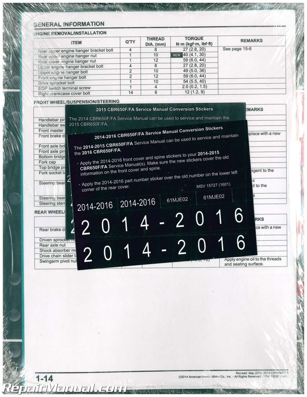
This Honda CBR650 F/FA Service Manual describes the proper methods and procedures for performing service, maintenance and repairs on 2014 2015 2016 Honda CBR650 F/FA motorcycles.
Table of Contents
General Information
Frame/body Panels/exhaust System
Maintenance
Pgm-fi System
Ignition System
Electric Starter
Fuel System
Cooling System
Lubrication System
Cylinder Head/valves
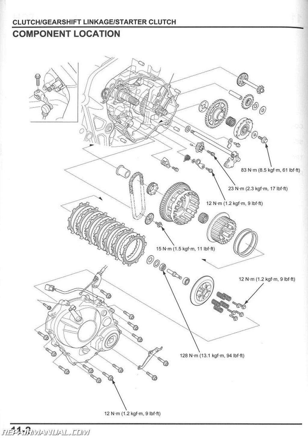
Clutch/gearshift Linkage/starter Clutch
Alternator
Crankcase/transmission
Crankshaft/piston/cylinder
Engine Removal/installation
Front Wheel/suspension/steering
Rear Wheel/suspension
Hydraulic Brake
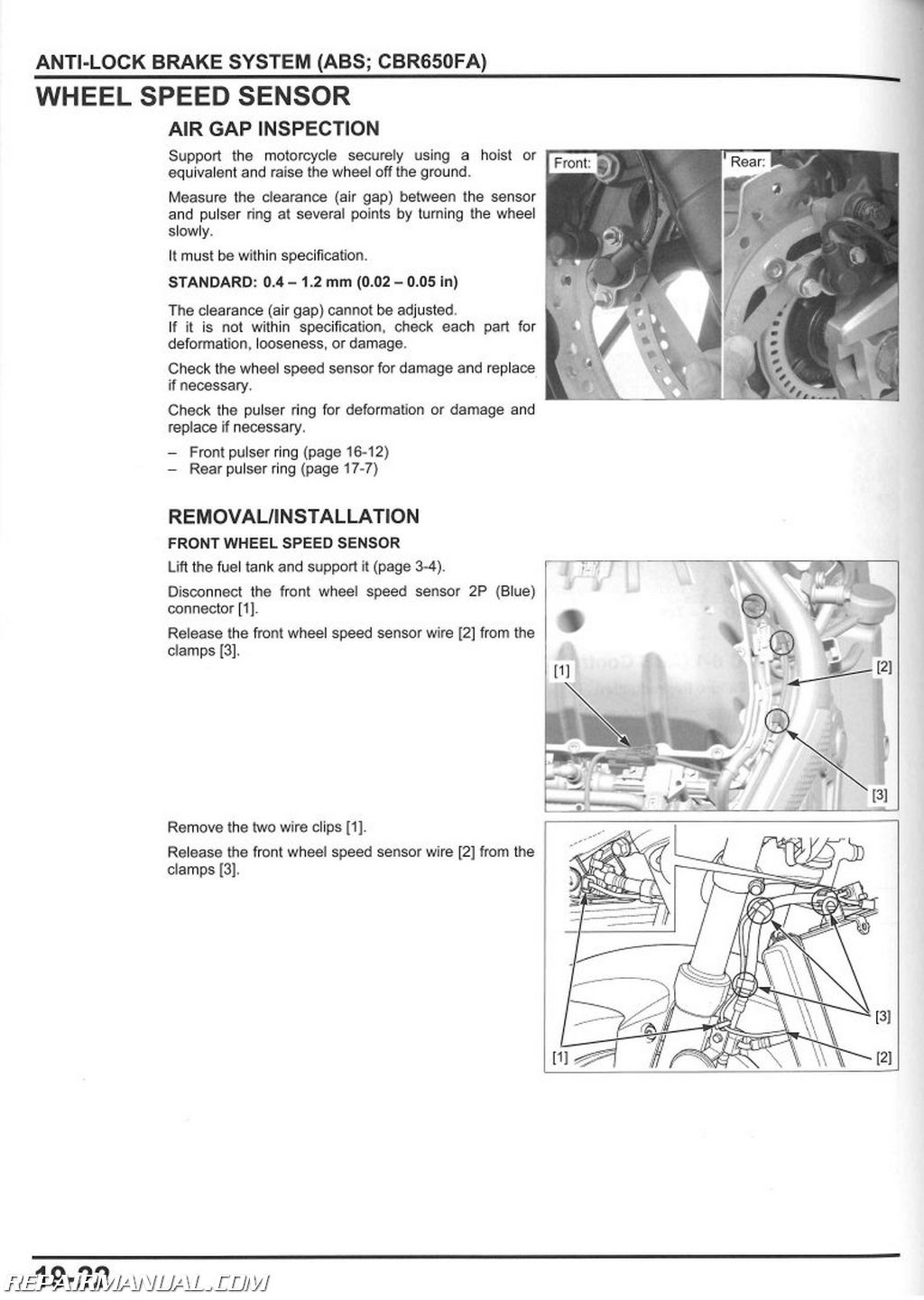
Anti-lock Brake System (abs; Cbr650fa)
Battery/charging System
Lights/meters/switches
Wiring Diagram
Index
Index of Topics
Abs Indicator Circuit Troubleshooting
Abs Modulator
Abs Troubleshooting
Abs Troubleshooting Information
Air Cleaner
Air Cleaner Housing
Alternator Charging Coil
Bank Angle Sensor
Battery
Body Cover
Body Panel Locations/removal Chart
Brake Fluid
Brake Fluid Replacement/air Bleeding
Brake Light Switch
Lights/meters/switches
Maintenance
Brake Pad/disc
Brake Pads Wear
Brake Pedal
Brake System
Brake/tail Light
Cable & Harness Routing
Cam Chain Tensioner Lifter
Camshaft
Charging System Inspection
Ckp Sensor
Clutch
Clutch Switch
Clutch System
Combination Meter
Component Location
Alternator
Clutch/gearshift Linkage/
Starter Clutch
Crankcase/transmission
Crankshaft/piston/cylinder
Cylinder Head/valves
Engine Removal/installation
Front Wheel/suspension/steering
Fuel System
Hydraulic Brake
Rear Wheel/suspension
Coolant Replacement
Cooling System
Cooling System Flow Pattern
Cooling System Testing
Crankcase
Crankpin Bearing
Crankshaft
Cylinder Compression Test
Cylinder Head
Cylinder Head Cover
Drive Chain
Drive Chain Cover/mud Guard
Drive Sprocket Cover
Dtc Index
Anti-lock Brake System (abs)
Pgm-fi System
Ecm
Ectsensor
Emission Control Systems
Engine Idle Speed
Engine Installation
Engine Oil Pressure Indicator/eop Switch
Engine Oil/oil Filter
Engine Removal
Evap Canister (ac Type Only)
Evap Purge Control Solenoid Valve (ac Type Only)
Evaporative Emission Control System (ac Type Only)
Exhaust Pipe/muffler
Fan Control Relay
Flywheel
Footpeg Bracket
Fork
Front Brake Caliper
Front Fender
Front Master Cylinder
Front Wheel
Fuel Gauge/fuel Level Sensor
Fuel Injector
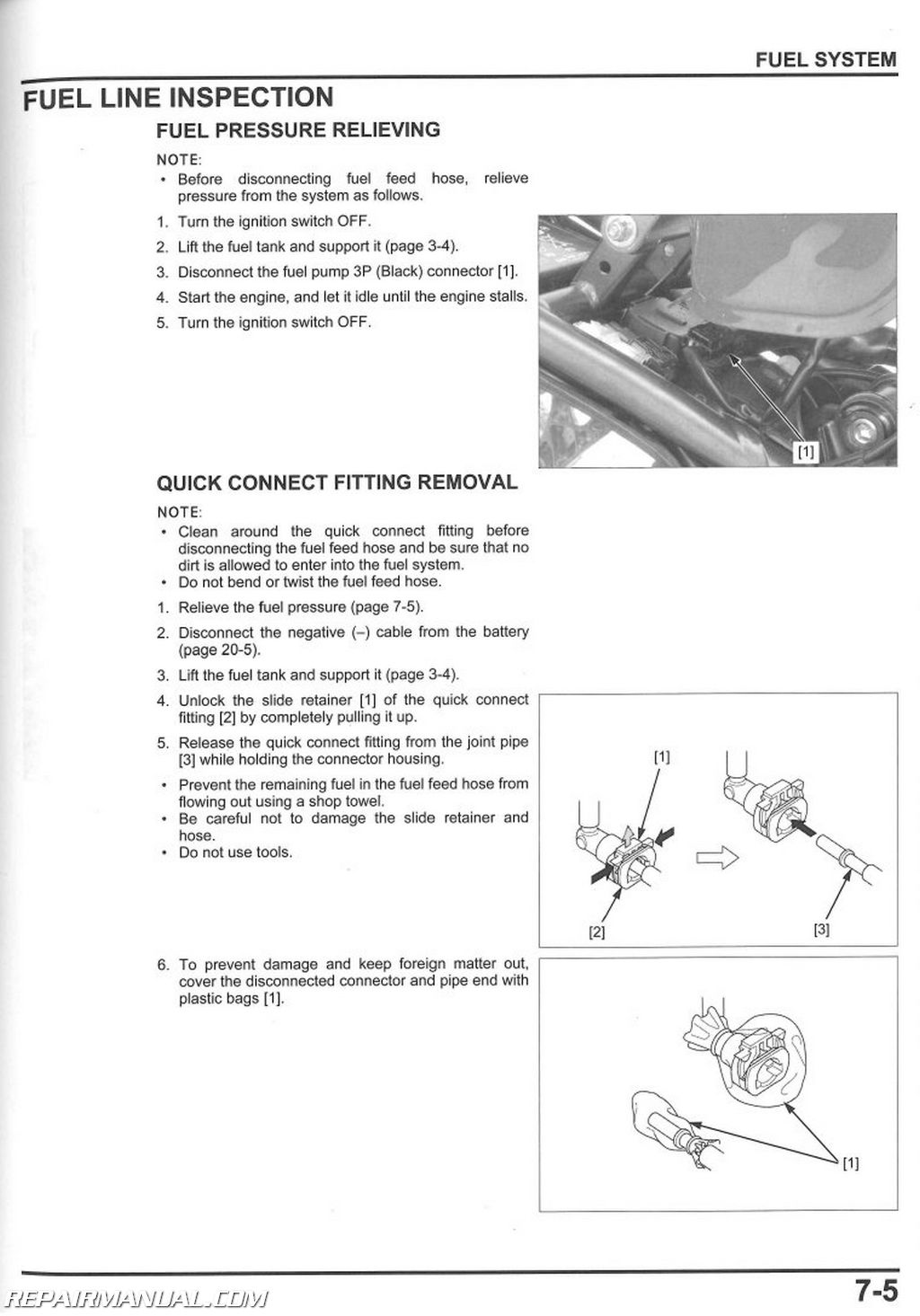
Fuel Line
Fuel Line Inspection
Fuel Pump Relay
Fuel Pump Unit
Fuel Tank
Gearshift Linkage
Handlebar
Handlebar Switch
Hazard Diode
Headlight
Headlight Aim
Headlight Assembly
High Coolant Temperature Indicator/ect Sensor
Horn
Iacv
Iat Sensor
Ignition Coil
Ignition Switch
Ignition System Inspection
Ignition Timing
Insulator
Left Crankcase Cover
License Light
Lubrication & Seal Points
Lubrication System Diagram
Main Journal Bearing
Main Relay
Main/fan Control/fuel Pump Relay
Maintenance Schedule
Map Sensor
Meter Panel
Middle Cowl
Mil Circuit Troubleshooting
Model Identification
Neutral Diode
Neutral Switch
Nuts, Bolts, Fasteners
O2 Sensor
Oil Cooler
Oil Pressure Inspection
Oil Pump
Oil Strainer
Pgm-fi Symptom Troubleshooting
Pgm-fi System Dtc Troubleshooting
Pgm-fi Troubleshooting Information
Piston/cylinder
Position Light
Pressure Relief Valve
Radiator Coolant
Radiator Reserve Tank
Radiator/cooling Fan
Rear Brake Caliper
Rear Cowl
Rear Fender A
Rear Fender B
Rear Fender Stay
Rear Master Cylinder
Rear Wheel
Rearview Mirror
Regulator/rectifier
Right Crankcase Cover
Seat
Secondary Air Supply System
Fuel System
Maintenance
Service Information
Alternator
Anti-lock Brake System (abs)
Battery/charging System
Clutch/gearshift Linkage/
Starter Clutch
Cooling System
Crankcase/transmission
Crankshaft/piston/cylinder
Cylinder Head/valves
Electric Starter
Engine Removal/installation
Frame/body Panels/exhaust System
Front Wheel/suspension/steering
Fuel System
Hydraulic Brake
Ignition System
Lights/meters/switches
Lubrication System
Maintenance
Pgm-fi System
Rear Wheel/suspension
Service Rules
Shock Absorber
Sidestand
Frame/body Panels/exhaust System
Maintenance
Sidestand Switch
Spark Plug
Specifications
Speedometer
Starter Clutch
Starter Motor
Starter Relay Switch
Stator
Steering Head Bearings
Steering Stem
Suspension
Swingarm
System Diagram
Anti-lock Brake System (abs)
Battery/charging System
Electric Starter
Ignition System
Pgm-fi System
System Location
Anti-lock Brake System (abs)
Battery/charging System
Electric Starter
Ignition System
Lights/meters/switches
Pgm-fi System
Tachometer
Technical Feature
Thermostat
Thermostat Case Assembly
Throttle Body
Throttle Operation
Torque Values
Tp Sensor Reset Procedure
Transmission
Troubleshooting
Battery/charging System
Clutch/gearshift Linkage/
Starter Clutch
Cooling System
Crankcase/transmission
Crankshaft/piston/cylinder
Cylinder Head/valves
Electric Starter
Frame/body Panels/exhaust System
Front Wheel/suspension/steering
Hydraulic Brake
Ignition System
Lubrication System
Rear Wheel/suspension
Turn Signal/hazard Relay
Turn Signal/position Light
Under Cowl
Upper Cowl A
Upper Cowl B
Valve Clearance
Vs Sensor
Water Hose Joint B
Water Pump
Wheel Speed Sensor
Wheels/tires
Windscreen
Wiring Diagram

