Description
This 300 page, Allis Chalmers 650 652 653 655 Crawler Tractor Dozer Loader Industrial Service Manual is a reproduction of the original, out of print, service manual. This manual provides detailed service information, step-by-step repair instruction and maintenance specifications for Allis Chalmers 650 Crawler Tractor, 652 653 Dozers, and 655 Loaders.
This manual will help you prevent minor irregularities from developing into serious conditions that might involve shutdown and major repair. The information you need to properly check and service your machine is included in great detail. it includes the proper maintenance intervals, lubrication information and how to perform all checks and services that will reveal the need for adjustment or change due to normal wear, which if neglected could result in failure and shut-down. This manual includes all the information you need to perform basic maintenance as well as a full overhaul.
Table of Contents
Specifications-Torques, Fits & Tolerances, & Trouble Diagnosis Check out Procedure
Engine
Fuel System
Electrical System
Seat, Fuel Tank, Hood Platform & Guards
Torque Converter
Torque Housing
Power Shuttle Clutch
Transmission
Bevel Pinion & Ring Gear
Final Drive
Steering Clutch
Brakes
Tracks
Hydraulic System
Index of Topics
Capacities
Fits and Tolerances
Flow Test Fittings
Hydraulic Symbols
Lubrication and Maintenance
Lubrication and Service Instructions
Specifications
Engine
General
Troubleshooting
Engine
Power Shuttle Clutch
Torque Converter
Torque Specifications
Front Support Plate
Fuel Injection Pump Drive Gear
Gear Train & Front Support Plate
Hydraulic Pump Drive Assembly
Housing & Gear
Idler Gear & Shaft
Intake Manifold
Lubricating System
Oil Flow Diagram
Oil Pan
Oil Pressure Pump
Assembly
Inspection of Oil Pump Parts
Installation
Pump Removal & Disassembly
Pistons & Piston Rings
Connecting Rods to Pistons
Timing Gear Cover & Crankshaft Front Oil Seal
Troubleshooting
Air Intake System
Cooling System
Electrical System
Engine
Fuel System
General
Instruments
Lubricating
Starting System
Valve Lifters
Automatic Speed Advance
Calibration Specifications
Fuel System
Cleaning
Fuel Filter
Priming the System
Fuel Injection Nozzle Holder Assembly
Cleaning
Timing Window
Fuel Injection Pump
Installation, Inspection, Removal
Hand Primer Pump
Installation, Inspection, Removal
Alternator
Batteries
General
Installation
Maintenance & Service
Operation
Storage
Testing
Delcotron
Generator
Pinion
Specifications
Starter
Charts & Tests
Removal & Installation
Starter Motor
Checking
Description
Disassembly
Inspection
Maintenance
Reassembly
Removal
Testing
Voltage Regulator
Checking Settings
Maintenance
Field Relay Points
Voltage Settings
Operation
Testing & Adjustment
Wiring Diagrams
Fuel Tank
Removal & Installation
Guards
Remove Lower Cover
Remove Rear Bottom Pan
Platform & Tanks
Installation
Removal & Assembly
Pusher Fan
Baffles
Fan Blades
Seat
Tank & Support
Cleaning & Inspection
Torque Converter Pump Assembly
Front Engine Mount & Bumper Stop
Installation
Bumper Stop Bracket
Performance
Yc Piggy Pump
Y-90 Flow Tester
Y-81 Flow Tester
Power Shuttle Clutch &
Torque Converter Hydraulic System
Change of Oil
Control Valve Clutch
Heat Exchange
Hydraulic System Check
Pressure Line Filter
Temperature Gauge
Torque Converter
Torque Housing –
Hydraulic Schematic
Torque Converter
Checking Parts
Installation
Pump
Assembly
Removal & Installation
Torque Converter Run Out
Check Out
Cold Check
Oil & Filters
Standing Check
Hollow Clutch Shaft
W/26 T Gear
Idler Shaft
Intermediate Shaft
Relief Valve (torque Converter)
Shuttle Clutch & Torque Converter
Stator Support Assembly
Torque Housing
Turbine Output Shaft Assembly
Turbine Shaft
Winch Drive
Cover Assembly
Drive Shaft
Idler Shaft
Shifter
Console & Hand Controls
Removal & Installation
Power Shuttle Clutch
Assembly & Disassembly
Illustration
Removal
Trouble Shooting
Power Shuttle Clutch Control Valve Assembly
Adjustment (relief Valve)
Checking Pressure (power Shuttle Clutch)
Directional Control Valve Spool
General Information
Modulating Valve
Trouble Shooting
Control Valve Disassembly
Relief Valve
Accumulator Valve
Modulator Valve
Shuttle Clutch & Torque Converter
Hose Arrangement
Schematic
Sump & Lines (illustration)
Tubes & Fittings
Transmission
Removal & Installation
Transmission Disassembly (h-4)
Assembly of First Gear Shift Rod & Fork
Assembly of Second & Third Shift Rod & Fork
Bearing Removal
Gear Shift Lever & Cover Assembly
Pinion Assembly & Removal
Pinion Shaft End Play
Removal & Assembly of Gear Shift Lever
Transmission Main Shaft
Assembly of Main Shaft
Front Bearing Removal
Rear Winch Drive Shaft
Seals & Bushings
Bevel Ring Gear
Backlash & Gear Tooth Contact Pattern
High Contact
Low Contact
Short Heel Contact
Short Toe Contact
Ring Gear & Carrier
Assembly
Removal
Final Drive
Assembly & Removal
Bearing Adjustment Procedure
Lubricate
Preload
Final Drive Axle Shaft
Assembly & Removal
Bearing Adjustment Procedure
Example
Final Drive Housing
Assembly & Removal
Rear Axle
Sprocket & Final Drive
Clutch Release Bearing and Fork
Power Steering
Adjustment
Control Rod
Control Valve
Hydraulic Schematic
Steering Cylinder
Free Travel
Removal
Rebuild
Pressure Plate
Steering Clutch
Assembly
Disassembly
First Method
Installation
Removal
Second Method
Steering Clutch Lever & Shaft
Adjustments
Brake Band Removal
Brake Adjustment Tool
Brake Lever Assembly
Brake Lever Removal
Brake Linkage & Clutch Shifter
Dimensions
Rollers
Support Rollers
Track Idlers
Track Side Bars (interlocking Track)
Drive Sprocket
Installation
Removal
Front Idler
Assembly
Disassembly & Removal
Installation & Adjustment
Inspection & Rebuilding
General Description
Grouser Wear
Grease Specifications (idler & Rollers)
Idler Flange Wear
Prolonging Undercarriage Life
Operating Techniques
Rail Assembly
Roller Flange Wear
Sprockets (full Sprocket)
Trabk
Track
Adjustment
Alignment
Frame
Hydraulic Track Adjuster
Idler & Rollers
Pin & Bushing Wear
Release
Removal
Roller Assembly & Disassembly
Roller Removal
Rollers
Service & Inspection
Support Rollers
Support Rollers Assembly & Disassembly
Tension Spring Removal
Track Guards
Turning Pins & Bushings
Wear Gauge
Wear Patterns
Control Valve
Disassembly
Dozer Control Valve Bank
Exploded View
Inspection ‘
Reassembly
Removal & Inspection
Section Identification (control Valve)
Valve Operation, Internal Diagrams
Cylinders
Loader
Dozer
Dozer Hydraulic (schematic)
Hydraulic Pump
Assembly
Disassembly
Installation
Removal
Hydraulic Reservoir
Filter
Installation
Magnet & Screen
Removal
Loader Hydraulic (schematic)
Pilot Operated Cushion Or
Relief Valve Pump Performance Chart
Performance Curve for YD 15 & 25 G P M
Specifications; (cylinders)
Trouble Shooting Chart


 SKU: AC-P-5050
 SKU: AC-P-6140
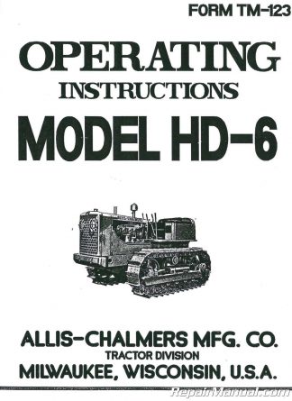 SKU: JS-AC-O-HD6
