Description
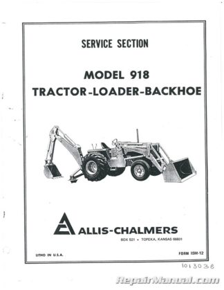
This 295 page, Allis Chalmers 918 Tractor Loader Backhoe Service Manual is a reproduction of the original out of print manual. This manual provides detailed service information, step-by-step repair instruction and maintenance specifications for Allis Chalmers 918 Tractor Loader Backhoes.
Table of Contents
Engine & Tractor Specifications – Torques, Fits & Tolerances
Fits & Tolerances (d-2800 Diesel Engine)
General Specifications
Stud Specifications & Torque
Torque Specifications (d2800 Diesel)
Diesel Engine Trouble Shooting
Camshaft Bearings
Camshaft & Camshaft Gear ]
Removal
Thrust Plate Inspection
Connecting Rod & Connecting Rod Bearings
Inspection
Rod Bushing Replacement
Crankshaft & Camshaft Gear
Crankshaft Removal & Installation
Inspection & Installation
Timing Marks
Crankshaft Pulley & Damper Assembly
Pulley Removal & Installation
Cylinder Block
Cylinder Sleeve
Cylinder Sleeve Reseating
Engine
Assembly
Cylinder Head (removal, Inspection)
Disassembly
General
Rocker Arms, Rocker Arm Shaft, Brackets & Push Rods, Removal,
Disassembly & Inspection
Run-In Schedule
Valves
Grinding
Valve Guide & Seating
Valve Spring
Valve Operating Mechanism
Engine Cooling System
Fan Belt Adjustment
General Maintenance
Schematic Diagram
Thermostat (removal-Testing)
Exhaust Manifold
Installation
Muffler
Removal
Flywheel & Engine Adaptor Plate
Engine Adaptor Plate Installation
Removal & Inspection (adaptor Plate)
Flywheel Gear
Flywheel Wear Sleeve
Installation & Removal
Front Plate & Gear Cover
Crankshaft Front Oil Seal
Timing Gear Cover
Front Support Plate
Fuel Pump Drive Gear & Pump Drive Shaft
Gear Train & Front Support Plate
Hydraulic Pump Drive Assy
Removal & Disassembly
Idler Gear & Shaft
Removal & Installation
Intake Manifold
Removal & Installation
Lubricating System
Main Bearings
Removal,inspection & Installation
Oil Pan
Oil Pressure Pump
Assembly
Engine Breather Tube
Inspection
Installation
Regulating Valve
Relief Valve
Removal & Disassembly
Pistons & Piston Rings
Connecting Rod & Bearing Installation
Connecting Rod to Piston
Fitting Piston Rings to Pistons
Fitting Rings to Cylinder Sleeves
Piston Ring Installation
Timing Gear Cover & Crankshaft
Front Oil Seal
Troubleshooting
Air Intake System
Checking Compression
Cooling System
Engine
Fuel System
Instruments
Lubricating System
Valve Lifters
Water Pump
Assembly
Disassembly
Installation
Removal
Wiring Diagram
Fuel Injection
Air Timing
Bench Test Procedure
Calibration Data
Centrifugal Governor
Disassembly (steps 1 Thru 17)
Parts Inspection (steps 1 Thru 22)
Checking Fuel System
Drive Shaft
Electrical Shut-Off
Fuel Injection Pump
Installation & Timing
Removal
Fuel Injection Nozzle Holder Assembly
Combustion Chamber
Dowel Location
Nozzle Holder Assy
Maintenance Tools
Roosa-Master Injection Pump
Construction & Operation
Fuel Flow (hand Priming & Pressure Regulator)
Return Oil Circuit
Priming Pump
Torque Control
Injection Pump
Tools Required for Roosa-Master
Torque Specifications
Troubleshooting
Torque Converter
Trouble Diagnosis Check-Out Procedure for Torque Converter Stall-Power Shuttle Clutch and Engine
Hollow Clutch Shaft (w/26 T Gear)
Checking End Play
Installation
Removal
Idler Shaft & Gears
Assembly
Removal
Intermediate Shaft & Gear
Assembly
Removal
Power Shuttle Clutch
Assembly
Disassembly
Stator Support Assembly
Assembly
Removal
Torque Converter
Check Engine
Check Power Shuttle Clutch
Check Torque Converter
Checking Hydraulic System
Checking Parts to Converter
Checking Run-Out
Checking Stator Support Assy
How to Change Torque Converter & Power Shuttle Clutch Oil
Installation
Note Installing Engine
Removal
Torque Converter
Torque Converter Relief Valve
Assembly
Removal
Torque Housing
Turbine Input Shaft
Removal
Turbine Output Shaft Assembly
Transmission
Bearing Information-918 Final Drive
Bench Assemble Pinion Shaft
Install Shaft & Gears in Housing
Brake Assembly j
Brake Adjustment
Brake Operation
Brake Pedals and Linkage
Disassembly
Installation
Removal
Countershaft & Gears
Installation
Removal
Final Drive & Rear Axle
Installation
Install Final Drive Pinion Shafts
Removal
Remove Final Drive Pinion Shafts
Four Pinion Differential Assembly
Assemble
Disassemble
Install Differential Assembly in Transmission Housing
Install Ring Gear to Differential
Input Shaft
Installation
Removal
Main Pinion Shaft & Gears
Installation
Adjust Bearing Assy
Chart
Select Pinion Shaft Bearing Snap Ring
Removal
Neutral Safety Switch Installation
Shuttle Clutch Sump & Manifold Lines
Transmission Assy
Installation
To Torque Housing
Main Frame to Tractor
Removal
Transmission Control Cover – Gear Shift
Assembly
Disassembly
Transmission Housing Specifications
Transmission Main Shaft
Transmission Shift Cover
Installation
Two Pinion Differential Assy
Assembly
Disassembly
Install Ring Gear to Differential Housing
Removal
Front Axle Assembly, Power Steering, Rear Wheel Assembly
Front Axle
Front Wheels & Bearing Adjustment
Adjustment
Removal
Power Steering
Cylinder
Ram
Valve
Disassembly
Reassembly
Rear Wheel
Installation
Puller Block Dimension
Tractor Hydraulic System
Hydraulic Pump Manifold
Oil Cooler & Lines
Oil Filter & Shuttle Clutch Lines
Power Shuttle Clutch Manifold Lines
Install Console and Hand Controls
Install Shuttle Clutch Valve
Power Shuttle Clutch Valve’
Adjustment
Assembly of Relief Valve
Assembly of Valve Spool
Checking Power Shuttle Clutch Pressure
Control Valve Body
Disassembly
Disassembly of Relief Valve
Disassembly of Valve Spool
General Information
Trouble Shooting
Remove Console and Hand Controls
Remove Shuttle Clutch Valve
Testinc Tractor Hydraulic System, Power Steering-Power Shuttle
Clutch & Torque Converter System
Torque Converter and Power Shuttle Clutch Hydraulic Pump (single)
Assembly
Disassembly
Specifications of Gears & Gear Plates
Integral Loader Main Frame
Main Frame
Installation
Installing Fuel Tank
Removal
Swing Frame, Boom, Dipper Stick & Loader Boom
Boom
Assembly
Disassembly
Inspection
Installation
Removal
Dipperstick
Assembly
Disassembly
Inspection
Removal
Loader Boom
Installation
Removal
Stabilizers
Installation
Removal
Swing Frame Assembly
Inspection
Installation
Removal
Swing Connecting Links
Installation
Removal
Swing Guide
Installation
Removal
Backhoe and Loader Control Levers
Backhoe Control Levers
Installation
Removal
Loader Controls
Installation
Removal
Control Valves and Relief Valves
Control Valves
Installation
Removal
Cushion Valve
Installation
Removal
Lift Checks
Loader Control Valve Bank
Installation
Removal
Relief Valves
Servicing Relief Valves
Inverted Poppet (number 4 Thru 6)
Pilot Operated (number 1,2,3)
Poppet Type (number 7)
Service Instructions for The Control Valves
Disassembly
Inspect Parts for Wear
Service Loader Control Valves
Disassembly
Inspect Parts for Wear
Reassembly
Swing Control Valve
Disassembly
Inspection
Installation
Reassembly
Removal
Trouble Shooting
Cylinders
Boom Cylinder
Bucket
Dipper
Boom Dipperstick Bucket & Stabilizer Cylinder Repair
Cylinder Inspection
Loader Bucket & Cylinder
Stabilizer Cylinder
Installation
Removal
Swing Cylinder
Connecting Hoses to LH
Connecting Hoses to RH
Installation
Removal
Hoses, Tubes and Fittings
Illustrations with Specifications of Fitting Sizes
Hydraulic Pump
Assembly
Disassembly
Removal
Large Volume System
Small Volume System
Suggested Tolerances
Bearings
Check Valves
Drive Shafts
Gears
Gear Housings
Seals and Gaskets
Thrust Plates


 SKU: JS-AC-P-B-1-ETC
 SKU: AC-S-6140
 SKU: JS-AC-S-715