Description
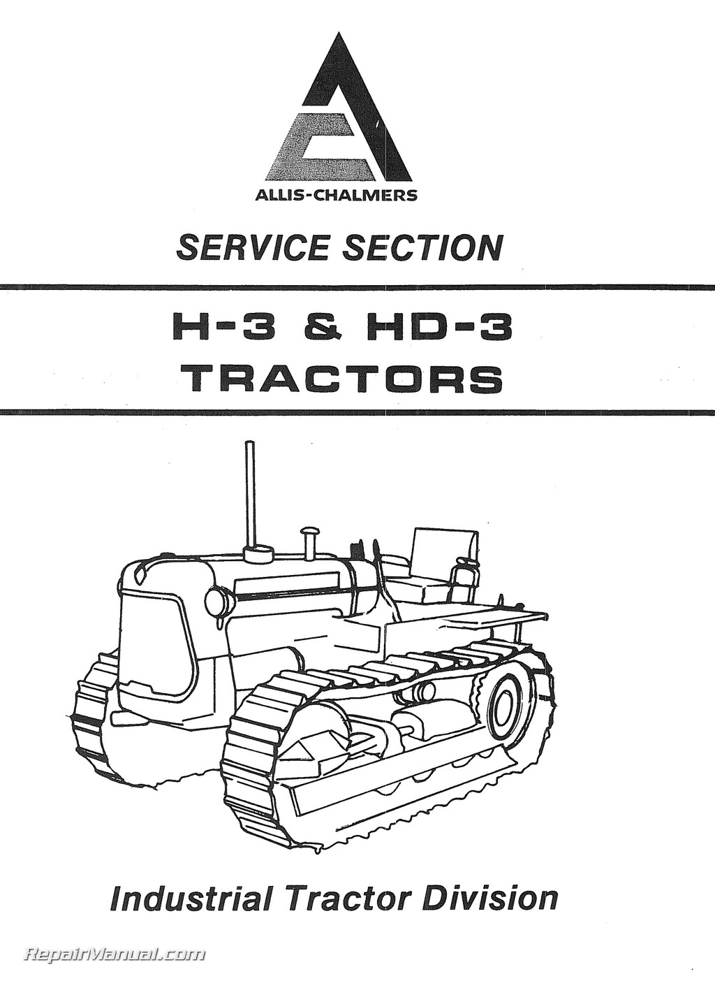
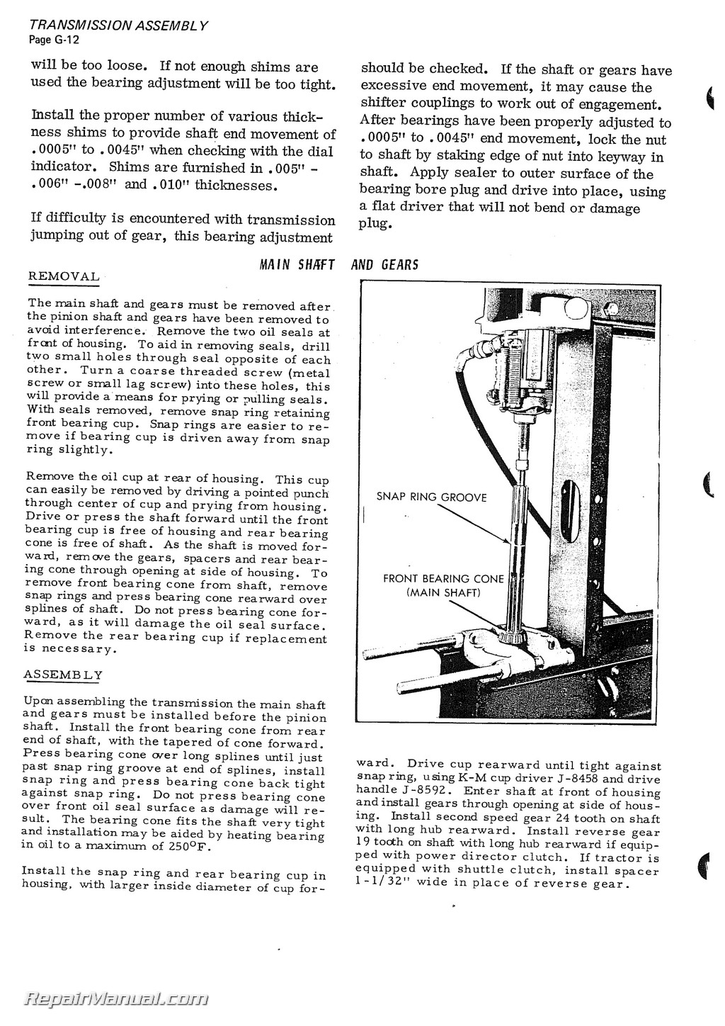
This 270 page, Allis Chalmers H3 HD3 Service Manual is a high quality reproduction of the original out of print manual. This manual provides detailed service information, step-by-step repair instruction and maintenance specifications for the Allis Chalmers H3 & HD3 tractors.
Table of Contents
149 Gasoline Engine (H-3 Crawler Tractor)
DISTRIBUTOR REMOVAL AND ASSEMBLY
ENGINE REMOVAL AND ASSEMBLY
Camshaft
Connecting Rod Beatings
Connecting Rods anil Pistons
Crankshaft and Main 8carings
Cylinder Head
Flywheel
Oil Pump
Oil Sump
Rocker Arm and Shaft
Thermostat
Timing – Gear Cover
Water Pump
GOVERNOR
Adjustment
Removal
Operation
SPECIFICATIONS
Engine Specifications
Fits and Tolerances
149 Gas Prior to S’N 69b9
160 Gas S/N 6969 – 8694
160 Gas S/N 8604 and up
Torque Specifications
TIMING THE ENGINE
Distributor Timing
Front Crankshaft Timing
Flywheel Timing
Carburetor
ADJUSTMENT
ASSEMBLY
High Angle Carburetor
TSX 879/TSX 912
GENERAL PRINCIPLES OF OPERATION
Choke System
Float System
Idle System
Power Fuel Feed System
REMOVAL OF CARBURETOR
Diesel Engine (HD-3 Crawler Tractor)
ENGINE REMOVAL AND DISASSEMBLY
Camshaft
Connecting Rods
Crankshaft
Cylinder Head
Cylinder Liners
Flywheel
Oil Pressure Relief Valve
Oil Pump
Oil Sump
Rear Oil Seal and Adaptor Plate
Rocker Arm Shaft
Thermostat
Timing Gear and Cover
SPECIFICATIONS {D175 ENGINE)
Fits and Tolerances of New Parts
TROUBLESHOOTING
Air Intake System
Cooling System
Electrical System
Engine
Fuel System
Lubricating System
Fuel Injection Pump
AIR TIMING
AIR OR ENERGY CELL
DISASSEMBLY
DRIVE SHAFT (INJECTION PUMP)
GENERAL TESTS AND BENCH TESTS
INSTALLATION
FUEL SYSTEM
Construction and Operation
A Components
B Fuel Flow
C Charging and Discharging
(Delivery Valve Type Rotor)
D Delivery Valve Function
E Return Oil Circuit
F End Plate Operation
G Centrifugal Governor
PARTS INSPECTION
PRIMING PUMP
REASSEMBLY (STEPS 1 THRU 22)
TRANSFER PUMP (DISASSEMBLY)
Metering Valve
NOZZLE HOLDER AND NOZZLE
Electrical System
BATTERY
Charging
Maintenance and Service
Operation
Specifications
Testing
GENERATOR
Disassembly and Testing
Reassembly and polarizing
REGULATOR
Adjustment
Action (Load Checks!
Current Operation and Cut out Relay Action
Current Voltage Regulator Action ,
Electrical Check
STARTING MOTOR GAS AND DIESEL
Cranking Motor Tests
Disassembly
Operation
Reassembly
WIRING DIAGRAM
Diesel
Gas
Torque Housing And Shuttle Clutch
TORQUE HOUSING
ASSEMBLY AND ALIGNMENT PROCEDURE
ENGINE CLUTCH SHAFT
HOLLOW SHAFT W/GEARS
IDLER SHAFT AND GEARS
INTERMEDIATE SHAFT AND GEARS
PIVOT AXLE BRACKET AND BUMP STOP BRACKET ,
POWER TAKE OFF SHAFT (FRONT)
SHUTTLE CLUTCH
ASSEMBLY
LEVER ADJUSTMENT
POWER DIRECTOR
REMOVAL AND DISASSEMBLY
Transmission Assembly
GEAR SHAFT
Assembly and Removal
Cover
Forward and Reverse Transmission
4 Speed and Power Director
HOUSING
MAINSHAFT AND GEARS
POWER TAKE OFF
Driven Shaft
Idler Shaft and Gears
PINION SHAFT AND GEARS
REAR PTO – SHAFT OIL SEAL
REVERSE IDLER GEAR
STANDARD AND POWER DIRECTOR TRANSMISSION GEARS
Final Drive, Steering Clutches And Brakes
FINAL DRIVE ASSEMBLY
AXLE SHAFT REMOVAL AND ASSEMBLY
FINAL DRIVE ASSEMBLY – PRELOAD
HOUSING REMOVAL AND ASSEMBLY
OIL LEVEL CHECK
SPROCKET AND FINAL DRIVE
STEERING CLUTCHES
ASSEMBLY
CLUTCH RELEASE BEARING AND FORK
INSTALLATION METHOD
REMOVAL
BRAKES
ADJUSTMENT (BRAKE BANDS)
BRAKE LATCH
BRAKE LEVER
PLUG ASSEMBLY FOR STEERING CLUTCH HOUSING
Tracks And Undercarriage
FRONT IDLER (EFF w/H-3 – HD-3 S/N 8298)
LUBRICATION
SPROCKET
TRACK FRAME
TRACK AND UNDERCARRIAGE
Adjustment
Wear Gauge
Alignment
Dimensions
Idler Wear Pattern Gauge
Roller Frame
Removal
Support Rollers
Prior to S/N (8298)
Eff w/H-3 S/N (8298)
Tension Spring
Hydraulic Pump
DRIVE AND MOUNTING
Eff w/Tractor S/N 8694 and up
FLO RATING (2 STAGE PUMP)
GENERAL INFORMATION
IDENTIFICATION AND PUMP REFERENCE NUMBERS
PUMP
Inspection
Alignment
Bearings
Dimensions Inspection
Drive Shaft and Seals
Gears and Gear Plate
Rings (Sealing, Loading and Backup)
Wear Plate
SINGLE STAGE 11 5 GPM PUMP
Removal, Disassembly and Assembly
2 STAGE 11 5-6 GPM PUMP
Removal, Disassembly and Assembly
Seals (End Section)
2JDS2-L, 4JDS3-L and 4JDS2-L
Removal, Disassembly and Assembly
TYPICAL PERFORMANCE CURVES
2JDS2-L Pump
4JDS3-L Pump
IYDS6/IYID6-LB Pump
IYDS6/OYD6-LB Pump
Control Valve
1 OR 3 SPOOL CONTROL VALVE
3 SPOOL CONTROL VALVE
Assembly
Oil Flow (Float, Lift and Lower Pisition)
Relief Valve
Valve Spool (Plunger Removal)
ANTI-CAVITATION LINE
HYDRAULIC PRESSURE SETTING
INSTALLATION OF CONTROL VALVE
LOADER HYDRAULIC CIRCUIT
Circuit Relief Valve
Assembly
Checking and Adjustment
Disassembly
Operation
Maintenance (Hydraulic Relief Valve)
Hydraulic Cylinders (service Information)
1066 LOADER, 1003SCARIFIER AND ATTACHMENTS
(w/Threaded Piston)
Assembly
Removal and Disassembly
1080,1081 AND 1090 DOZER
(Lift, Angle and Hydraulic Till Cylinders)
Removal, Disassembly and Assembly

