Description
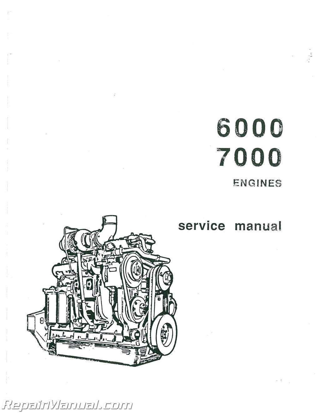
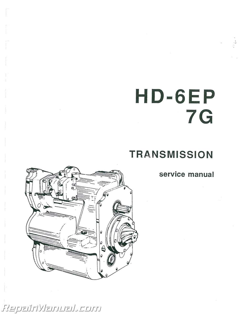
This 530 page, Allis Chalmers HD-6E, HD-6EP Crawler Tractor, 7G, 7G-B Crawler Loader Service Manual (6000 and 7000 Diesel Engine) Service Manual is a reproduction of the original out of print manual. This manual provides detailed service information, step-by-step repair instruction and maintenance specifications for Allis Chalmers HD-6E, HD-6EP Crawler Tractors, 7G, 7G-B Crawler Loaders.
The 6000 and 7000 engines covered in this manual are both four cylinder, vertical in-line, four cycle, water cooled, open combustion chamber, direct injection, full diesel engines. The main difference between the two models is that the 6000 engine is naturally aspirated and the 7000 engine is turbocharged. Fuel is supplied to the cylinders by a constant stroke, cam-actuated, multi-outlet, single and distributing-plunger, sleeve control type fuel injection pump. The pump delivers accurately metered quantities of fuel, under high pressure, through fuel injection nozzles, into the cylinders at a definite timing in relation to the engine firing cycle. The fuel is ignited by heat generated by compression of the air in the cylinders. A combustion chamber is located in the head of each piston and the fuel injection nozzles are mounted in the cylinder head. The orifices in the tip of the nozzle are drilled at a slight angle so that the fuel is sprayed directly into the combustion chamber which is slightly offset toward the camshaft side of the engine. The shape of the combustion chamber, angle of fuel injection, and the shrouded intake valves, causes extreme turbulence of the air within the cylinders and results in the fuel and air being thoroughly mixed for complete combustion. The engines are full pressure lubricated by a gear type oil pump driven by the crankshaft gear. Engine cooling is accomplished by coolant, forced through the engine cooling and radiator system by a centrifugal type water pump. The water pump is belt driven.
Table of Contents
Description and Specifications
Cooling System
Electrical System
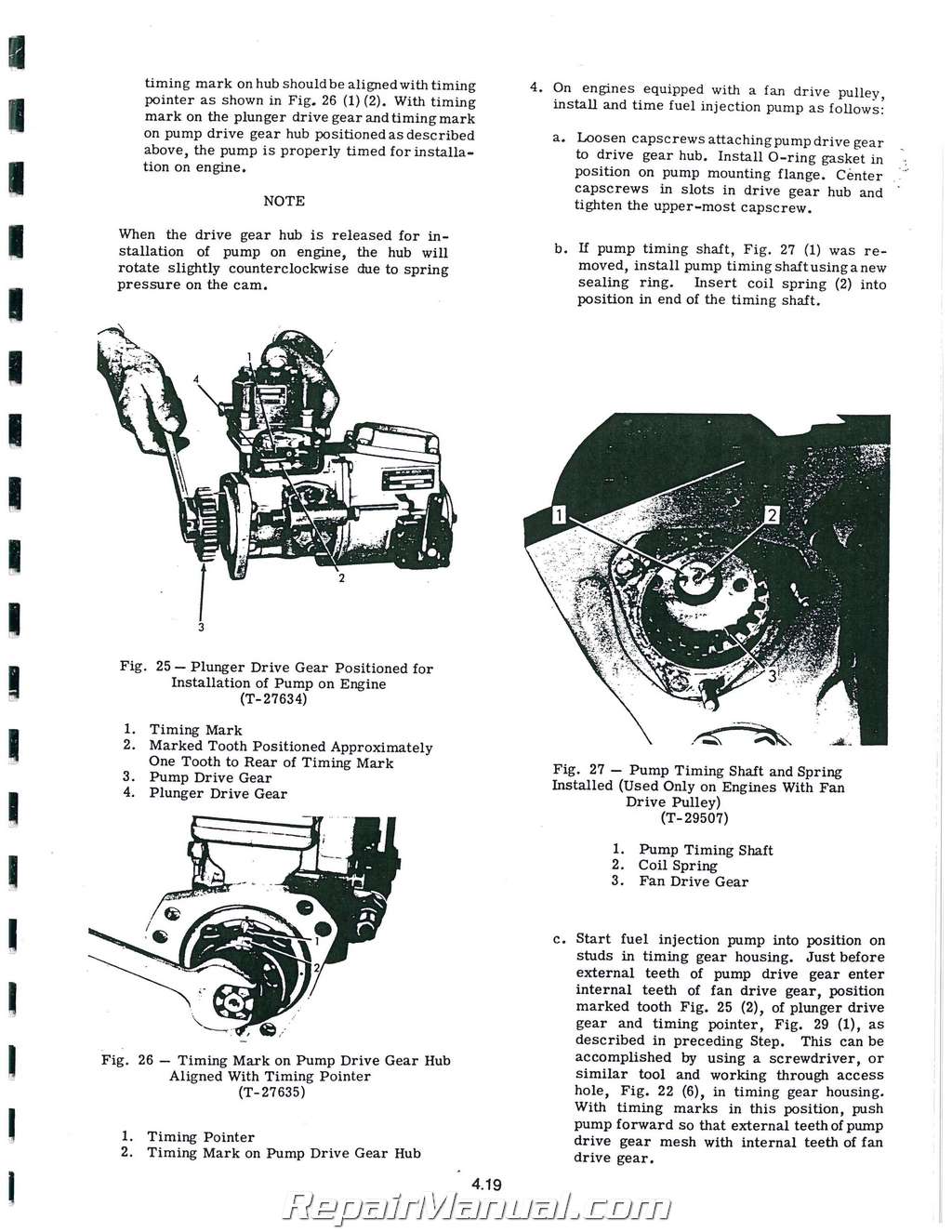
Fuel System
Air Cleaner and Intake Manifold
Exhaust Manifold and Turbocharger
Valves, Valve Operating Mechanism, and Cylinder Heads
Front End and Gear Train
Flywheel and Ring Gear; Flywheel Housing and Crankshaft Rear Oil Seal
Lubricating System
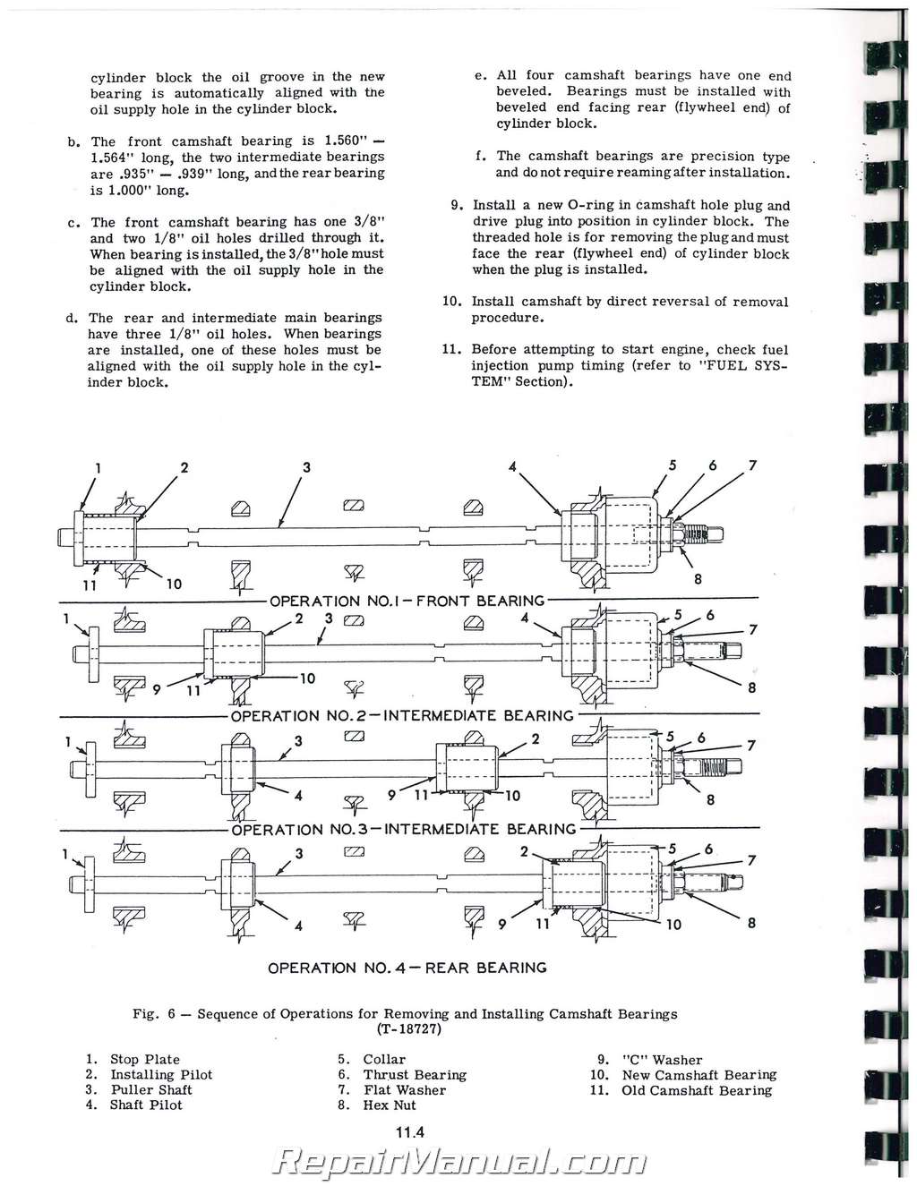
Camshaft and Camshaft Bearings
Pistons, Piston Rings, Connecting Rods, and Connecting Rod Bearings
Crankshaft and Crankshaft Gear, Main Bearings, and Main Bearing Caps
Cylinder Block and Cylinder Sleeves
Engine Removal and Installation
Engine Disassembly and Assembly
Fits and Tolerances and Torque Specifications
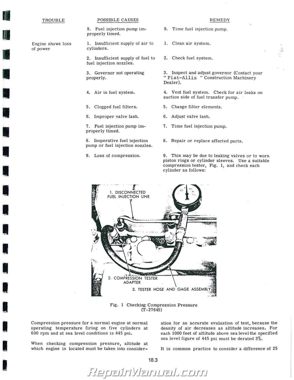
Trouble Shooting
Service Tools
Also covers the Final Drives on HD-6E.HD-6EP: S/N 14484 thru 22250 / 70C 22251 – UP, 88Y 22251 – UP
7G.7G-B: S/N 22222 THRU 27950 / 34U 27951 – UP
Final Drive Table of Contents
GENERAL DESCRIPTION
TROUBLE SHOOTING
FINAL DRIVE DISASSEMBLY
3 1 Removal of Track Sprocket and Shaft
3 2 Removal of Final Drive Intermediate Shaft
3 3 Removal of Final Drive Pinion Shaft
FINAL DRIVE ASSEMBLY
4 1 Installation of Final Drive Pinion Shaft
4 2 Installation of Final Drive Intermediate Shaft
4 3 Installation of Track Sprocket Shaft and Sprocket
4 4 Installation of Sprocket Shaft outboard Bearing and Cage
4 5 Installation of Steering Clutches, Track Frame, and Track
4 6 Lubricant Specifications and Capacity
FITS AND TOLERANCES
SERVICE TOOLS
CONVERSION TABLES
Also includes coverage for HD-6, HD-11 HD-16, HD-21 crawler tractors and 6G, 7G, 7G-B 11G, 21G crawler loaders in the included UNDERCARRIAGE service manual.
Models covered and their effective serial numbers are as follows:
HD-6A…………… S/N 15730-UP
HD-6AG………….. S/N 15730 – 22250, 94S 22251 – UP
HD-6B…………… S/N 15730-22250, 40M 22251 – UP
HD-6E…………… S/N 15730 -22250, 70C 22251 – UP
HD-6EP………….. S/N 16007-22250, 88Y 22251 – UP
6G……………… S/N 15620-22250, 37A 22251 – UP
7G……………… S/N 22793 – 27200
7G-B……………. S/N 27201 – 27950, 34U 27951 – UP
HD-11…………… S/N 7538 – 14650
HD-11 AG………… S/N 7538- 14650, 17L 14651 -UP
HD-11E………….. S/N 7538- 14650, 29C 14651 – UP
HD-11EP…………. S/N 7538- 14650, 46Y 14651 – UP
11G S/N 6427-UP
HD-16………….. S/N 5616 – 9550
HD-16DC S/N 5616-9550, 24L 09551 – UP
HD-16DP…………. S/N 5616- 9550, 64A 09551 – UP
HD-21 A…………. S/N 12368-UP
HD-21 P…………. S/N (ALL)
21G…………….. S/N 11725-UP
UNDERCARRIAGE service manual Table of Contents
GENERAL DESCRIPTION
UNDERCARRIAGE ALIGNMENT CHECKS
A On Tractor Alignment Checks
B Off Tractor Alignment Checks
C Straightening Truck Frame
TRACK
A Adjustment
B Track Removal
C Track Installation
D Track Rebuild (Sealed and Non-Sealed)
TRACK IDLERS
A Description
B Maintenance
C Removal of Track Idler
D Disassembly of Track Idler
E Inspection of Track Idler Components
F Rebuilding Track Idler
G Assembly of Track Idler
H Installation and Alignment of Track Idler
1 General Information
2 Installation and Alignment
TRACK SUPPORT ROLLERS
A Description
B Maintenance
C Disassembly of Support Rollers
1 HD21 Models
2 HD16 Models
3 HDU, HD7G, 7G Series B, and HD6 Models
D Inspection of Support Roller Components
E Assembly of Support Rollers
1 HD21 Models
2 HD16 Models
3 HD11, HD7G, 7G Series B, and HD6 Models
TRUCK WHEELS
A Maintenance
B Checking and Removal of Truck Wheels
C Disassembly of Truck Wheels
D Inspection of Truck Wheel Components
E Assembly and Installation of Truck Wheels
TRACK RELEASE
A HD16 and HD21 Models
1 Removal of Track Release
2 Inspection of Track Release
3 Installation of Track Release
B HU11 Models
1 Removal of Track Release
2 Inspection of Track Release
3 Installation of Track Release
C HD6E, EP, HD7C, and 7G Series B Models
1 Removal of Track Release
2 Inspection of Track Release
3 Installation of Track Release
D HD6A, B, and G Models
1 Removal of Track Release
2 Inspection of Track Release
3 Installation of Track Release
TRUCK FRAMES
A Description
B Removal of Truck Frame
1 All Models Except ’’G” Models
2 “G” Models
C Removal and Installation of Pivot Shaft, Seals, and Bushing –
All Models
D Inspection of Truck Frame
E Installation of Truck Frame
1 All Models Except ”G” Models
2 “G” Models
3 Installation of New Shovel Frame Rear Anchor Lug –
HD21G Only
TRUCK FRAME AND TRACK COMPONENT REBUILD DIMENSIONS
A General Information
B Track Side Bar Dimensions
C Support Roller Dimensions
D Track Idler Dimensions
E Truck Wheel Dimensions
F Truck Frame Dimensions
G Track Guiding Guard Dimensions
FITS AND TOLERANCES
A HD6, HD7G, and 7G Series B Models
B HDU
C HD16
d hd2i
E Track Pin Dimensions
F Track Bushing Dimensions
SERVICE TOOLS
CONVERSION TABLES
Major components of undercarriage are: truck frame, truck wheels, track support rollers, track release, track idler, and track (each side). Truck frame is fabricated from special steel sections welded into a rigid frame. Bottom of truck frame and idler location on top of truck frame are machined parallel co within a few thousands of an inch to pro- vide accurate alignment of truck frame to track idler and truck wheels. Each truck frame is secured at rear by pivot shaft and sprocket shaft outboard bearing; pivot shaft is secured to bottom of steering clutch and final drive housing by pivot shaft caps. Sprocket shaft outboard bearing is installed in sprocket shaft outboard bearing cage; truck frame is attached to outboard bearing cage by capscrews. Truck frames support tractor main frame by use of a rigid beam (oscillating beam or spring assembly on some models). Truck wheels revolve on tapered roller bearings and are attached to truck frames by capscrews inserted through attaching brackets and threaded into replace- able tapped blocks. Track support rollers and track idlers revolve on tapered roller bearings; internally their construction is similar to truck wheels. Track idlers are held in lateral position by idler brackets; idlers are held in forward position by track release. Idler brackets are guided on truck frames by replaceable slide bars. Truck wheels, track support rollers, and track idlers contain positive type grease seals and are lubricated for life at time of assembly. No further lubrication service is required on these assemblies except when they are being reassembled after repair. Three types of track release mechanisms used in various models are: non lubricated and direct acting coil springs used on HD6B-E-EP and HD6G tractors; oil lubricated and enclosed direct acting coil spring on HD7G, 7G Series B and HD11 B-E-EC and EP tractors; bell crank mechanism and oil lubricated coil springs on all HD 16 and HD21 tractors. Truck frame guard equipment (special equipment on most models) consists of track guiding truck wheel guards, track idler guards, and guards for track sprocket. Truck wheel guards, Fig. 1, are an important factor in extending the useful life of truck wheels and track rail assembly. Under certain operations or when track is extremely loose, track rails have tendency to leave truck wheels and move to the side (to the point where track rails are beneath truck wheel flange). Guards, Fig. 1, will keep track rail assembly inline with truck wheels, preventing any misalignment.
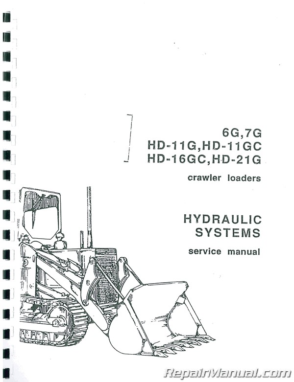
Also covered in this manual is the HYDRAULIC SYSTEM Service Manual for 6G,7G, HD-11G,HD-11GC, HD-16GC, HD-21 G crawler loaders:
6G S/N 101-22250, 37A 22251-UP
7G S/N 22222-27200
HD-11G.GC S/N 101-UP
HD-16GC S/N 101-UP
HD-21 G S/N 7001-UP
HYDRAULIC SYSTEM Service Manual Table of Contents
GENERAL DESCRIPTION
HYDRAULIC SYSTEM DESCRIPTION
A Introduction
B Characteristics of Main Components
C Oil Flow
OIL SPECIFICATIONS, CAPACITIES, AND SERVICE
A Oil Specifications and Capacities
B Service
TROUBLE SHOOTING
A Specification Chart
B Troubles and Remedies
C Pressure Checking
D Flow Checking with Circuit Tester
CONTROL VALVES
A Description
B Removal
C Disassembly
D Inspection
E Assembly
F Installation
PUMPS
A Description
B Pump Mounting and Drive
C Removal and Installation
D HD6G, HD7G (Hydreco)
E HD6G, HD7G (Tyrone #GPA 3-300 AT)
F HD6G, HD7G (Tyrone #20300-A)
G HD11G (Hydreco)
H HD16G, HD21G (Hydreco)
CYLINDERS
A Description
B Rod Packing Replacement
C Piston Packing Replacement
D Piston Rod Wiper Seal Replacement
E Cylinder Removal and Installation
SHOVEL AND SHOVEL LINKAGE
A Description
B Removal and Installation
MULTI-PURPOSE BUCKET (HD6G, HD7G)
A Description
B Hydraulic System and Oil Capacity
C Trouble Shooting and Pressure Checking
D Control and Safety Valves
E Clam Cylinders
F Bucket Removal and Installation, and Multi-Purpose
Positioning Indicators
G Fits and Tolerances
SHOVEL FRAMES AND STABILIZER
A Description
B Removal and Installation
FITS AND TOLERANCES
A Pumps
B Cylinders
C Control Valves
SERVICE TOOLS
CONVERSION TABLES

