Description
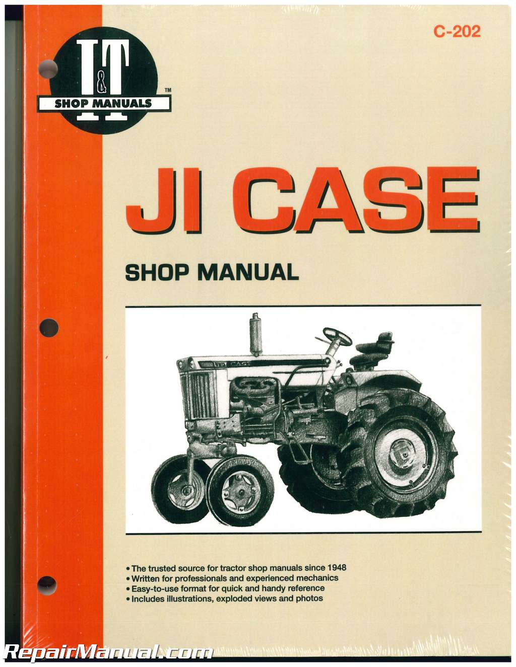
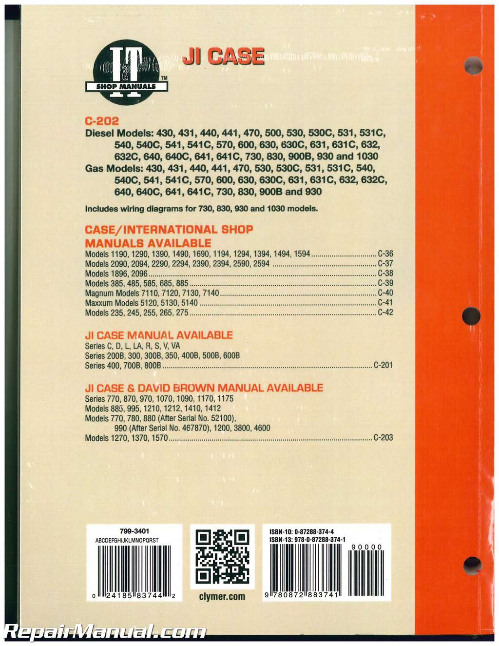
This 264 page, JI Case David Brown Tractor Repair Manual provides detailed service information, step-by-step repair instruction and maintenance specifications for JI Case and David Brown Series 430, 440, 470, 500, 530, 540, 570, 600, 630, 640, 730, 830, 900B, 930 and 1030 tractors.
Table of Contents
Axle, Front
Belt Pulley
Brakes
Chain, Final Drive
Clutch
Engine (traction) clutch, Engine (traction) clutch shaft, removal, Power take-off clutch
Cooling System
Differential
Diesel System
Bleeding, Filters, Fuel relief valve, Injection pump APE and PES (internal drive), Injection pump PES (external drive), Injection pump PSB, Injection pump timing APE and PES (internal drive), Injection pump timing PES (external drive), Injection pump timing PSB, Nozzle (injector) removal, Nozzle (injector) testing, Nozzle servicing, Powercells (precombustion cells)
Electrical
Generator and regulator, Starting motor
Engine
Assembly R&R, Cam followers, Camshaft, Connecting rods R&R, Connecting rods and bearings, Crankshaft and bearings, Crankshaft front seal, Cylinder heads, Cylinder sleeves, Decompressing linkage, Flywheel, LP-Gas System, Main bearings, Oil pan, Oil pump and relief valve, Piston and rod removal, Piston pins, Piston rings, Pistons, Rocker arms, Tappets (cam followers), Timing gear cover, Timing gears, Valve guides and springs, Valves and valve seats
Final Drive and Transmission
Bevel gears, Bull pinion sprocket, Bull sprocket, Chains, driving, Clutch shaft (traction), Differential, Driving chains, First reduction shaft /Reverse idler, Second reduction shaft, Shifter rails and forks, Sliding gearshaft, Sprockets, driven, Sprockets, driving, Top cover, Wheel axle bearings, Wheel axle shaft and housing
Front System and Steering
Axle, front, Bleeding power steering, Control valve, power steering, Cylinder, power steering, Pivot pin, front axle, Pressure test, power steering, Pump and valve, power steering, Spindle arms and bushings, Spindle and bushings, Steering gear, adjust, Tie rod and drag link
Governor
Diesel, LP-Gas
Lift System
Components of system, Control valves, Fluid and filling, Oil filter, Pump, Pump drive chain, Relief valve adjustment, Speed regulator valve, Troubleshooting
LP-Gas System
Adjustments, Filter, Regulator
Power Take-Off
Clutch plates, Clutch drum and bearing, Drive shaft, Drive sleeve, External (stub) shaft, Sump housing and drive shaft, remove
Steering Gear
Torque Recommendations Table
Transmission
This Manual includes wiring diagrams for 730, 830, 930 and 1030 models.

