Description
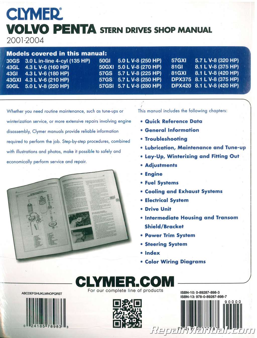
This Clymer 2001 2002 2003 2004 Volvo Penta Stern Drive Shop Manual provides detailed service information, step-by-step repair instruction and maintenance specifications for 2001-2004 Volvo Penta stern drives. Includes 30GS (3l inline 4 cyl), 4.3GL, 4.3GI and 4.3GXI (4.3L V-6), 5.0GL, 5.0EI and 5.0GXI (5L V-8), 5.7GS, 5.7GSI and .(5.7L V-8), 8.1GI, GIGXI, DPX3.75 and DPX4.20 (8.1L V-8). Features 688 illustrated pages. We’ve personally used this manual to assist in diagnosing a problem with a Volvo Penta engine that had a running condition problem. The engine was hard to start and required 3/4 throttle to get it going. It would regularly stall and finally the fuel pump started whining really bad. We were able to use this manual to run all the troubleshooting tests and determined the fuel regulator was clogged as well as the fuel cell. This manual showed us how to properly remove and replace the fuel cell and get the boat back in the water quickly.
Table of Contents
QUICK REFERENCE DATA
CHAPTER ONE | GENERAL INFORMATION
Manual organization | Warnings, cautions and notes | Safety | Model identification | Engine operation | Fasteners | Shop supplies | Galvanic corrosion | Propellers | Basic tools | Special tools | Precision measuring tools | Electrical component replacement | Electrical system fundamentals | Basic mechanical skills | Specifications
CHAPTER TWO | TROUBLESHOOTING
Electrical component replacement | Preliminary inspection | Electric starting system | Charging system | Ignition system | Basic fuel system troubleshooting | Carburetor fuel system | Electronic fuel injection (EFI) system | Diagnostic trouble codes | Power steering system | Power trim electrical system troubleshooting | Power trim hydraulic system troubleshooting | Cooling system troubleshooting | Warning system | Engine troubleshooting | Drive system | Specifications
CHAPTER THREE | LUBRICATION, MAINTENANCE AND TUNE-UP
Before each use | After each use | Lubrication | Fuel system maintenance | Engine coolant | Tune-up | Submersion | Specifications
CHAPTER FOUR | LAY-UP, WINTERIZING AND FITTING OUT
Lay-up | Winterizing | Fitting out
CHAPTER FIVE | ADJUSTMENTS
Carburetor adjustment | Ignition timing adjustment | Shift cable and linkage adjustment | Throttle cable adjustment | Trim position sender and trim limit control module adjustment | Specifications
CHAPTER SIX | ENGINE
Engine operation | Special tools | Replacement parts | Special service precautions | Engine removal/installation | Engine alignment | Rocker arm cover | Valve adjustment | Placing the No. 1 piston at TDC (firing position) | Lifter cover | Camshaft lobe lift measurement | Cylinder head | Rocker arm and pushrod | Flywheel housing | Drive coupler | Drive plate | Flywheel | Flywheel pilot bearing | Output drive shaft, seals and bearings | Oil pan | Oil pump | Harmonic balancer | Timing gear/chain cover | Timing chain and sprockets | Balance shaft | Camshaft and lifters | Piston and connecting rod | Rear main seal and rear main seal carrier | Crankshaft | Break-in procedure | Specifications
CHAPTER SEVEN | FUEL SYSTEMS
Fuel system service | Mechanical fuel pump | Low-pressure electric fuel pump | Carburetor | Electronic fuel injection (EFI) | Intake manifold | Specifications
CHAPTER EIGHT | COOLING AND EXHAUST SYSTEMS
Thermostat | Hose replacement | Recirculation pump replacement | Seawater pump | Oil and power steering fluid cooler replacement | Exhaust elbow | Exhaust bellow and flapper valve | Exhaust tube and flapper valve | Exhaust manifold | Specifications
CHAPTER NINE | ELECTRICAL SYSTEM
Battery | Alternator | Starter motor and solenoid | Starter relay | Fuel pump relay | EFI system relay | Ignition system | Oil pressure sender | Oil pressure switch | Engine temperature sender | Engine temperature sensor | Engine overheat switch | Exhaust overheat switch | Intake air temperature sensor (IAT) | Throttle position sensor (TPS) | Idle air control motor (IAC) | Knock sensor | Knock sensor module | Engine control unit (ECU) | Warning horn replacement | Specifications
CHAPTER TEN | DRIVE UNIT
Drive unit service precautions | Drive unit identification | Drive unit operation | Drive unit gear ratio | High altitude operation | Outdrive service precautions | Sacrificial anodes | Shifting and propeller rotation | Propeller | Drive unit removal and installation | Upper drive shaft housing | Universal joint | Shift housing service | Pressure and vacuum test | Specifications
CHAPTER ELEVEN | INTERMEDIATE HOUSING AND TRANSOM SHIELD/BRACKET
Intermediate housing operation and inspection | Intermediate housing and suspension fork | Transom shield and mounting collar | Transom bracket (SX, DP-S and XDP models) | Transom bracket (DPX models) | Specifications
CHAPTER TWELVE | POWER TRIM SYSTEM
Trim relay | Trim switch fuse | Trim limit control module | Trim motor | Trim pump | Fluid reservoir | Fluid screen | Hydraulic pump | Relief valve | Trim cylinder | Trim hose | Trim position sender | Filling and bleeding the trim system | Specifications
CHAPTER THIRTEEN | STEERING SYSTEM
Safety precautions | Mechanical (manual) steering system | Power steering system | Specifications
INDEX
WIRING DIAGRAMS


 SKU: IOS-6
 SKU: UB770
 SKU: SL3604-041-1
