Description
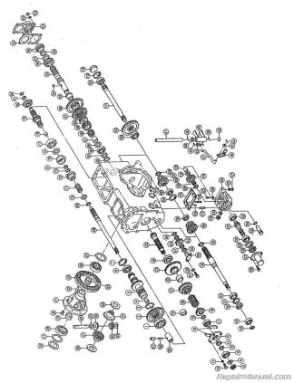
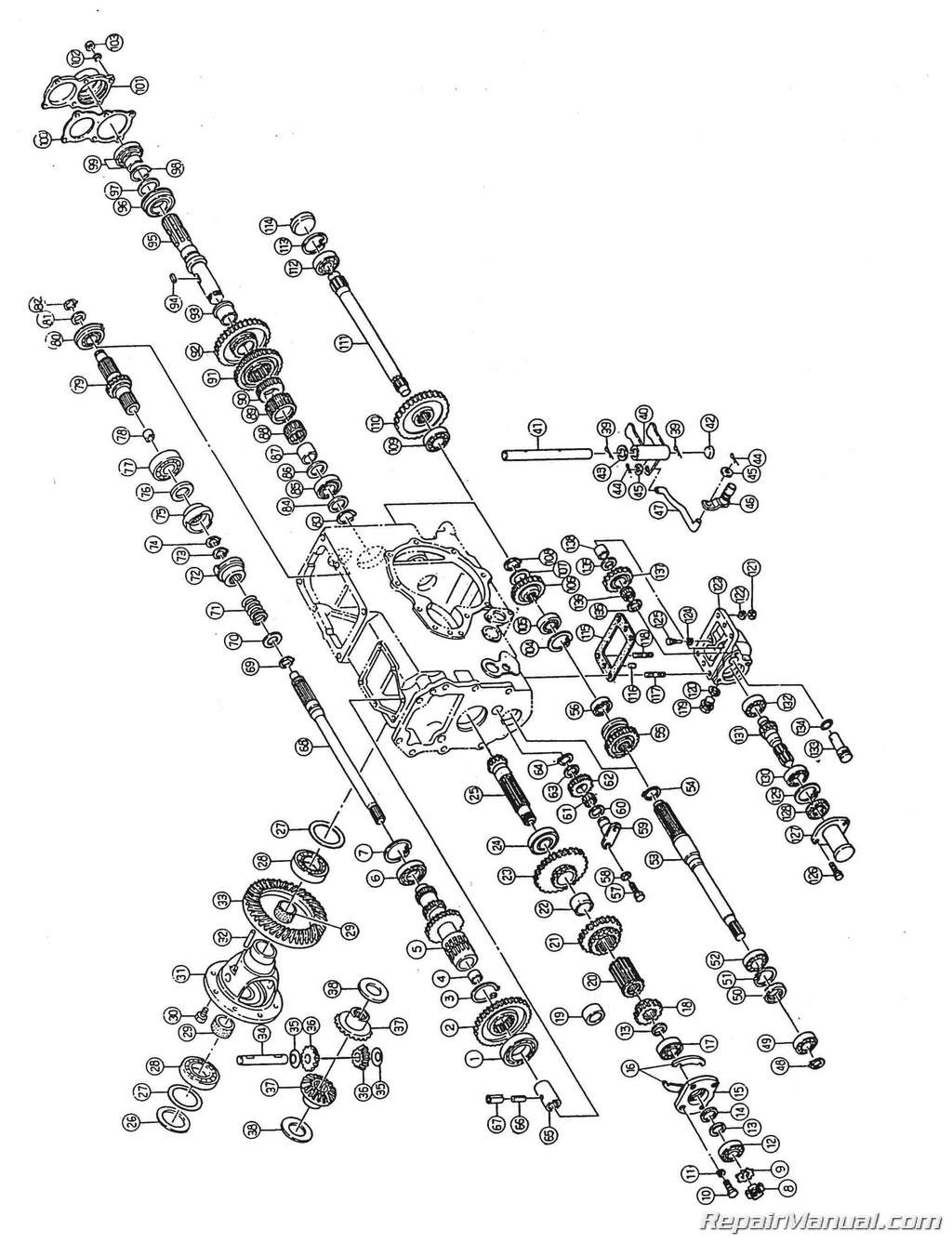
This 330 page, Deutz-Allis 5215 Diesel Compact 3 Cylinder 4WD Service Manual is a reproduction of the original out of print manual. This printed manual provides repair information for Deutz-Allis 5215 Diesel Compact 4WD tractors.
The engine used in the Deutz-Allis 5215 4WD Diesel Compact Tractor was developed exclusively for agricultural use and to withstand overloads and severest condition of use. It consistently provides top performance as long as it is kept properly maintained per the procedures described in this service manual. This 3-cylinder, 4-cycle, swirl chamber engine uses an indirect injection system. Forced lubrication with a trochoid pump and water cooling insure greater reliability. Cylinders are sleeveless. Four precision crankshaft bearings inserts and two selective connecting rod bearings are used. The cylinder head is shaped to provide swirl chambers, which are of the dry type. Grow plugs are installed in the swirl chambers. The crankshaft has a timing gear and a pulley at front. The main bearings use steel-backed Kelmet linings with lead-plated bearing surfaces for smoothness and durability. Crankshaft thrust is maintained by the center main journal with thrust washers which are separate from the crankshaft bearings. The thrust bearings are a Babbit alloy. The pistons are the taper and oval skirt type and are made of an aluminum alloy. Three rings are installed on the piston. Connecting rods are forged. A replaceable precision bearing insert is at the large end. The connecting rod bearing inserts use steel backed Kelmet linings and lead-plated bearing surfaces for smoothness and durability. The flywheel and the crankshaft are precisely balance to prevent engine vibration. Purchase this Deutz-Allis 5215 4WD Diesel Compact Tractor Service Manual to keep your compact tractor running in tip top shape!
Table of Contents
Engine
DESCRIPTION
SPECIFICATIONS
FITS AND TOLERANCE OF ENGINE PARTS
Cylinder and Piston
Piston Ring
Crankshaft and Main Bearings
Connecting Rods and Piston Pin (press fit type)
Connecting Rod Bearings
Exhaust Valve
Intake Valve
Exhaust Valve Seat Ring (cylinder head)
Intake Valve Seat Ring (cylinder ring)
Valve Guide (cylinder head)
Rock Arms
Valve Lifter
ENGINE TORQUE SPECIFICATIONS
BOLT TORQUE SPECIFICATIONS
DISASSEMBLY AND ASSEMBLY
Intake and Exhaust Manifolds
Disassembly and Assembly
Rocker Cover
Disassembly and Assembly
Valve Lash Adjustment
Valve Timing
Rocker Arm Assembly
Disassembly and Assembly
Rocker Assembly
Disassembly and Assembly
Cylinder Head
Disassembly
Assembly
Servicing the Cylinder Head
Inspection
Swirl Chamber Insert
Disassembly and Assembly
Valve Springs
Disassembly
Inspection
Assembly
Valve Seat Grinding
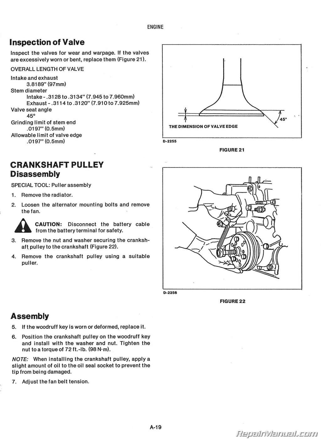
Inspection of Valve
Crankshaft Pulley
Disassembly and Assembly
Timing Gear Case
Disassembly
Assembly
Servicing
Idler Gear
Disassembly and Assembly
Camshaft Drive Gear
Disassembly and Assembly
Idler Pump Gear
Disassembly
Assembly
Hydraulic Pump Drive Gear
Disassembly
Assembly
Adjustment of End Play
Front Plate
Disassembly and Assembly
Flywheel
Disassembly
Inspection
Assembly
Rear Plate
Disassembly
Inspection
Crankshaft Rear Oil Seal
Disassembly and Assembly
Engine Sump (Oil Pan)
Disassembly and Assembly
Oil Screen
Disassembly and Assembly
Oil Pump
Disassembly and Assembly
Servicing the Oil Pump
Diassembly
Servicing the Oil Pump Cover (Relief Valve)
Disassembly and Assembly
To Check Oil Pressure
Injection Camshaft
Diassembly and Assembly
Camshaft
Disassembly
Inspection
Valve Lifters (Tappets)
Disassembly
Inspection
Assembly
Connecting Rods (Big End Bearings)
Disassembly
Inspection
Assembly
Piston and Connecting Rods
Disassembly and Assembly
Fuel Injection System
GENERAL
BLEEDING THE FUEL SYSTEM
FUEL FILTER
Disassembly and Assembly
Servicing the Fuel Filter
INJECTION PUMP
Construction
Operation
Plunger Operation
NOZZLE AND HOLDER
Construction
Opeation
INJECTION PUMP AND GOVERNOR
Construction
PUMPMODES
Stop
Start
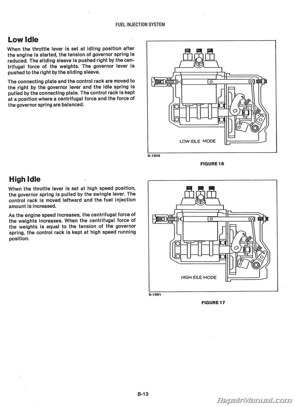
Low Idle
High Idle
Maximum Load
HANDLING FUEL
Damage Caused by Bad Fuel
Care of the Fuel System
FUEL INJECTION PUMP
Removal
Installation
Disassembly
Outline for Disassembly
Inspection
Assembly
Installation
ADJUSTMENTS
Injection Timing
Stopper Bolt
Idle Set Screw
Speed Set Screw
Ungleich Unit
Damper Bolt
UNGLEICH UNIT
Adjustment
Procedure
FUEL INJECTORS
Disassembly and Assembly
HANDLING OF NOZZLE AND NOZZLE HOLDER
Disassembly
Inspection
Repair
Assembly
Adjustment
TROUBLE SHOOTING
Engine Does Not Start
Rotation Speed of Engine is Erratic
Engine Cannot Attain Maximum Rotation Speed
Top Rotational Speed Too High
Output of Engine is Insufficient
Hydraulic System
GENERAL
POSITION CONTROL
3 POINT HITCH HYDRAULIC SYSTEM
CONTROL FUNCTIONS
Position
Floating
During Implement Lift
During Implement Lowering
HYDRAULIC CYLINDER
Removal and Installation
Disassembly
Reassembly
HYDRAULIC CYLINDER ADJUSTMENTS
Lift Arm Range
Lever Operation Force
Control Valve and Link
Floating Range
CONTROL VALVE ASSEMBLY
Disassembly
Check
Assembly
COVER ASSEMBLY
Disassembly and Assembly
Check
Adjustment of Relief Valve Pressure
RATE OF LOWER CONTROL
Faster Rate
Slower Rate
Lowering Lock
GEAR PUMP
Removal
Disassembly
Assembly
Inspection
TROUBLESHOOTING
REMOTE VALVE OIL CIRCUIT
VALVE PACKAGE INSTALLATION
VALVE HANDLE EXTENSION KIT FOR HYDROSTATIC
1 Spool
Installation
Plumbing of Tractor Auxiliary Valve
Parts List
2 Spool
Installation
PI umbi ng of Tractor Auxl 11 ary Valve
Parts List
VALVE HANDLE EXTENSION KIT FOR SYNCHRO SHIFT
1 Spool
Installation
PI umbi ng of T ractor Auxi I iary Valve
Parts List
2 Spool
Installation
PI umbi ng of T ractor Auxi I i ary Valve
Parts List
Power Train
Hydrostatic Transmission
SPECIFICATIONS
SPLITTING THE TRACTOR BETWEEN FRONT AXLE AND ENGINE
Splitting Procedure
SPLITTING THE TRACTOR BETWEEN ENGINE AND CLUTCH HOUSING
Splitting Procedure
SPLITTING THE TRACTOR BETWEEN CLUTCH HOUSING AND HST HOUSING
Splitting Procedure
SINGLE CLUTCH
CLUTCH ASSEMBLY
Disassembly, Assembly and Inspection
CLUTCH CONTROL
Disassembly, Assembly and Inspectlon
CLUTCH PEDAL
Neutral Operation
HST UNIT DESCRIPTION
CHECKING PRESSURE
Charge Pressure
High Relief Pressure
Drain Relief Pressure
CONTROL LINKAGE
Tightening Torques and Grease Points
CONTROL LEVER
Adjustment and Greasing Point
HST UNIT
Removal and Disassembly
Description and Specifications
HST UNIT DISASSEMBLY
Port Block
Motor Section
Pump Section
Charge Pump
PumpSlash Plate
Reference Values andAllowable Limits
HST UNIT ASSEMBLY
Pump Swash Plate
Pump Shaft and Charge Pump
Pump Cylinder Block Section
Motor Section
Port Block
Port Block and Case
Troubleshooting
Range Transmission and Rear Main Housing Parts List
DISASSEMBLY AND ASSEMBLY
Spacer Housing and Spacer Housing Assembly
Transmission
Countershaft
Shift Control
Drive Pinion and Differential
Differential Assembly
ADJUSTMENT
Differential Assembly
Preload and Pinion Height
Ring Gear Backlash and Differential Bearing
Check of Tooth Contact
4 WD TRACTOR DISASSEMBLY AND ASSEMBLY
Front Drive Idler Shaft
Front Drive Shaft and Front Drive Shift Control
Rear Axle and Brake Parts List
BRAKE ASSEMBLY
Disassembly and Assembly
BRAKE SHOES AND DRUM
Inspection and Adjustment
Troubleshooting
REAR AXLE UNIT
Removal
Assembly and Disassembly
Adjustment of End Play
DIFFERENTIAL LOCK LINKAGE
Disassembly and Assembly
MID PTO CASE ASSEMBLY
Removal and Replacement
Disassembly and Assembly
PTO SHAFT
Disassembly
Assembly
PTO DRIVE SHAFT
Disassembly and Assembly
PTO SHIFT CONTROL
Disassembly and Assembly
PTO EXTENSION SHAFT
Disassembly and Assembly
MID PTO SHAFT
Disassembly and Assembly
Synchro Shift Transmission
SPECIFICATIONS
GENERAL
TRACTOR SEPARATION
CLUTCH ASSEMBLY
Removal
Check
Assembly
CLUTCH CONTROL
Disassembly
Check and Assembly
SLEEVE ASSEMBLY
Removal
Disassembly and Assembly
Installation
AXLE
Axial Clearance Adjustment
DIFFERENTIAL LOCK LINKAGE
Disassembly
Assembly
FRONT DRIVE SHAFT
Disassembly
Assembly
PTO SHAFT
Disassembly and Assembly
Separate Rear Housing from Transmission U nit
DIFFERENTIAL ASSEMBLY
Disassembly and Assembly
Check
RING GEAR BACKLASH
Adjustment
TOOTH CONTACT CHECK
TRANSMISSION
SHIFT COVER
Assembly
MAIN SHAFT
Disassembly and Assembly
COUNTER SHAFT
Disassembly
C heck
Axial Clearance Adjusment
COUNTERSHAFT
Assembly
REVERSE IDLER GEAR
Disassembly
Axial Clearance Adjustment
RANGE SHIFT
Disassembly
Assembly
DRIVE PINION SHAFT
ADJUSTMENTS
Beari ng Case Clearance
Pinion Height
DRIVE PINION SHAFT
Axial Clearance Adjustment
Installation
PTO SHIFT
Disassembly and Assembly
PTO SAFETY SWITCH
PTO SHAFT
Adjustment
BRAKE
Disassembly and Assembly
Front Axle, 4 Wheel Drive
GENERAL
Front Axle Cross Section
4 Wheel Drive
GEAR CASE COVER ASSEMBLY
Removal
Replacement and Disassembly
Assem bI y
CASE SUPPORT AND LIFT BOLT
Disassembly and Assembly
FRONT AXLE
Disassembly
I n spect i on
As se m b I y
Reassembly
FRONT GEAR CASE
Disassembly
FRONT AXLE CASE
Disassembly
Asse m b I y
DIFFERENTIAL CARRIER AND BEVEL PINION
Disassembly
Inspection
Assembly
DIFFERENTIAL ASSEMBLY
Disassembly and Assembly
Inspection
BEVEL PINION ADJUSTMENTS
Preload (Initial Torque)
Pinion Height
Backlash
TOOTH CONTACT
Inspection
Correction
FRONT AXLE UNIT
Disassembly
Assembly
Adjustment of End Play
Electrical System
ELECTRICAL SYSTEM WIRING DIAGRAM
BATTERY
HYDROMETER TEST
Charge Method
INSTRUMENTS AND CONTROLS
TACHOMETER
Disassembly and Assembly
LIGHT SWITCH
General
Disassembly and Assembly ,
KEY SWITCH
General
Disassembly and Assembly
LEGEND PANEL
Alternator Warning Light
Low Fuel Level Light
Engine Oil Pressure
Glow Lamp
Legend Panel Disassembly and Assembly
Bulb Replacement
FUEL LEVEL SENDING UNIT
Disassembly and Assembly
OIL PRESSURE SWITCH
Disassembly and Assembly
GLOW PLUGS
Disassembly and Assembly
TEMPERATURE WARNING LIGHT
Disassembly and Assembly
COOLANT TEMPERATURE SWITCH
Disassembly and Assembly
FLASHER UNIT
Disassembly
FUSE BLOCK
Disassembly and Installation
STARTER SAFETY SWITCHES
General
Disassembly
Testing
Installation
Bulbs
VOLTAGE REGULATOR
Testing
ALTERNATOR
Alternator Components
Disassembly and Assembly
Testing
TROUBLESHOOTING
STARTER
SPECIFICATIONS
MAGNETIC SWITCH
Disassembly
REAR COVER AND BRUSH HOLDER
Disassembly
YOKE AND ARMATURE
Disassembly
PINION GEAR
Disassembly
STARTER TESTING
Yoke (Field Coil) Check
Insulation Check
Armature Check
Armature Insulation Check
ARMATURE ASSEMBLY
Commutator Check
Insulator Check
Armature Shaft Check ,
BRUSH HOLDER CHECK
Brush Movement and Inspection
Holder Insulation Check
Brush Spring Tension
MAGNETIC SWITCH
Shunt Coil Check
Serial Coil Check
Pinion Check
TROUBLESHOOTING
Chassis
HOOD ASSEMBLY
Removal and Adjustment
HOOD RELEASE
Disassembly and Assembly
INSTRUMENT PANEL
Disassembly and Assembly
CENTER CONSOLE AND FENDERS
Disassembly and Assembly
FOOT RESTS
Disassembly and Assembly
FUELTANK
Disassembly and Assembly
HAND THROTTLE LINKAGE
Disassembly and Assembly
Adjustment
MANUAL STEERING
General
Di sassembly
Reassembly
FRONT AXLE, TWO WHEEL DRIVE
TOE IN
Adjustment
FRONTHUB
Inspection and Reassembly
SPINDLE SHAFT
Disassembly and Assembly
FRONT AXLE CENTER BEAM
Inspection
Assembly
CENTER SECTION
Disassembly and Assembly
SPINDLE HOUSING BUSHINGS
Disassembly and Assembly


 SKU: JS-WI-S-VH4
 SKU: JS-KOM-S-D20AP-PLUS
 SKU: JS-DE-S-ENG912-PLUS