Description
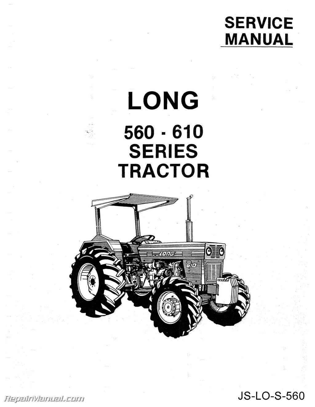
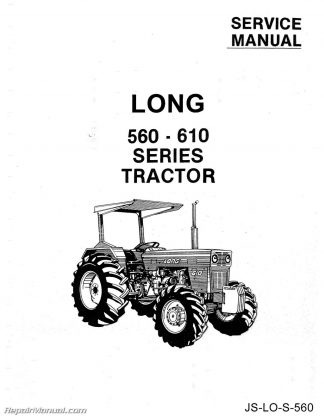
This 197 page Long 560, 610 Series Factory Service Manual provides detailed service information, step-by-step repair instruction and maintenance specifications for Long 560 4 Cylinder Diesel, Long 610 4 Cylinder Diesel tractors. This Long 560 610 Tractor Service Workshop Repair Manual is a high quality reproduction of the original out of print manual.
The following excerpt is from the manual:
TIMING GEAR ASSEMBLY
To gain access to the timing gears remove the case cover as outlined under “Cam-shaft Removal”. Remove the timing gears from the case as follows:
1. Camshaft driving gear (see instructions under “Camshaft Removal”.)
2. Idler gear: remove snap ring first, then withdraw it together with the two thrust washers.
3. Fuel supply pump driving gear. First remove the pump with its camdrive gear bearing then remove the shaft retaining ring and withdraw the shaft with gear.
4. Injection pump driving gear back out the attaching nut functioning as puller. Fig. A.11/12 illustrates the correct position of assembly of the camshaft driving gear (Item VII) and of the other fuel injection pump (Item V) and transfer pump (Item IV) gears. The injection pump gear is marked with the engine model designation and the angular position of the number 4 indicating the mesh with respect to the shaft key:
Install the timing gears as follows:
1. Bring piston 1 to T.D.C. and turn the crankshaft clockwise until the pointer is in registerwith the ‘‘P.M.S. 1″ mark stamped on the flywheel rim.
2. Install feed and injection pump driving gears on respective shafts and line up the assembly marks 4-4.
3. Install then the idler and timing gears and line up the pairs 1-1, 2-2, 3-3.
4. Tighten the gear capscrews to tabulated torque values in “Torque Specifications” table.
Long 560 610 Tractor Service Manual Table of Contents:
ENGINE INDEX: Specifications – Removal – Installation, Description, Specifications , Fault-Finding, Removing Engine from -Tractor, Disassembly and Reassembly, Installation Crankcase – Cylinder Head – Oil Sump, Grankcaseand Cylinder Liners, Checking and Cleaning the Crankcase, Cylinder Liner Re-boring and Replacement, Cylinder Head , Oil Sump Valves and Timing Mechanism, General, Timing Data, Camshaft, Valves,Guides and Springs, Valve Gap Adjustment, Tappets, Push-Rods and Rocker Arms, Timing Gear Assembly, Tachourmeter Crank Gear Assembly, General, Crankshaft, Crankshaft Bearings, Pistons and Rings, Connecting Rods, Engine Flywheel Fuel System, Air Supply , Fuel Supply, Fuel Tank, Fuel Priming Pump, Fuel Filters
CAV INJECTION PUMP – General Description, Injection Pump Removal, Pump Installation and Timing, Injectors, Starting Aid Lubrication, General, Oil Pump, Oil Filter, Low Oil Pressure Warning Light, Lube and Capacity Chart Cooling, General, Water Pump, Radiator, Thermostat, Fan, Water Temperature Gauge, Balancing Mechanism, Removal, Dismantle, Inspect and Re-assembly Fits and Tolerances – Torque – Specifications, Balancing Mechanism, Fits and Tolerances 560, Fits and Tolerances 610, Torque Specifications
POWER TRAIN INDEX: Foreward Description, Transmission Performance Data, Lubricants Clutch, 11″ Clutch, Description, Removal, Disassembly, Inspection, Assembly, Adjustment Transmission, 8 Speed Transmission, Removal, Disassembly, Inspection, Assembly, Installation Bevel Gear and Differential, Description, Removal, Disassembly, Inspection, Assembly, Bevel Gear Setting Brakes, Description, Disassembly, Inspection, Assemble, Adjustment Independent Hand Brake, Description, Disassembly, Assemble, Adjustment Final Drives and Rear Wheels, Description, Removal, Disassembly, Inspection, Assembly Power Take-Off, Overhauling Front Axle and Steering, Steering Box, Removal, Disassembly, Inspection, Assembly, Adjustments Front Axle and Steering, Description, Overhaul, Front Axle Checks Front Drive Axle (Side Drive), Front Drive Axle, Removal, Disassembly, Inspection, Assembly, Bevel Pinion Setting, Reduction Gear, Description, Removal, Disassembly, Inspection, Assembly, Installation Front Drive Axle (Center Drive), Front Drive Axle, Description, Removal, Planetary Drive, Removal, Disassembly, Inspection, Reassembly, Axle Shaft, Removal, Disassemble, Inspection, Reassemble, Differential, Removal, Disassemble, Inspection , Reassemble, Reduction Gear, Removal, Disassemble, Inspection, Reassemble, Installation Data, Fits, Wear Limits Torque Specifications, Fit and Tolerances, Torque Specifications
HYDRAULIC LIFT AND POWER STEERING INDEX: GENERAL SPECIFICATIONS HYDRAULIC LIFT, Mechanics of Position Control Operation, Mechanics of Draft Control Operation, Removal – Disassembly, Inspection, Assembly and Installation, Oil Filter, 3-Point Linkage, Adjustment, Checking Pressure Relief, Safety and Drain Valves
REMOTE HYDRAULIC SYSTEM HYDRAULIC PUMP, Overhauling, Trouble-Shooting Chart
POWER STEERING
HYDROSTATIC STEERING
FITS AND TOLERANCES
TORQUE SPECIFICATIONS
ELECTRICAL SYSTEM
BATTERY CHARGING PLANT – Wiring Diagram, General, Alternator, Alternator Specifications, Alternator Operation, Rectifying Diodes, Diode Specifications, Checking Diodes, Service Instructions, Rectifier Diode Replacement, Alternator Disassembly, Alternator Assembly, Replacing the Brushes, Installation on the Tractor, Operation Instructions, Maintenance Instructions
VOLTAGE REGULATOR
BATTERY CHARGE WARNING LIGHT RELAY – Trouble Shooting the Battery Charging System, Trouble Shooting Guide in Case of Irregular Warning Light Operation
STARTER – Starter Characteristics, Test Instructions for Starter Check, Trouble Shooting Instructions, Service Instructions, Starter Dismantling, Reassembly, Inspection and Permissible Repairs, Troubles, Causes and Remedies, Specifications, Starter

