Description
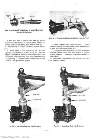
This Massey Ferguson MF300 Diesel Crawler Loader and Angledozer Service Manual provides detailed service information, step-by-step repair instruction and maintenance specifications for Massey Ferguson MF300 diesel Crawlers.
Table of Contents
ENGINE
DESCRIPTION
ENGINE TROUBLESHOOTING
ENGINE
Removal
Installation
ROCKER ARM SHAFT ASSEMBLY
Removal
Replacement
Adjusting valve clearance
Disassembly
Inspection and servicing
Reassembly
CYLINDER HEAD
Description
Removal
Replacement
Disassembly and inspection
Reassembly
Valves, Valve Seats, Valve Springs
Valves
Removal and inspection
Servicing
Valve seats
Inspection
Servicing
Installing valve seat inserts
Replacing an existing valve seat insert
Valve springs
PISTON AND CONNECTING ROD ASSEMBLY
Description
Removal
Separating pistons from connecting rods
Installing pistons onto connecting rods
Installing piston and connecting rod assemblies
Checking
— Connecting rods
— Bushing replacement
Piston pins
Pistons and rings
CRANKSHAFT AND MAIN BEARINGS
Description
Renewing main bearings with crankshaft in place
Crankshaft end-play
Replacing thrust washers
Removing the crankshaft
Installing the crankshaft
Inspecting the crankshaft
— Regrinding the crankshaft
Rear crankshaft oil seal
— Removing oil seal retainers
— Oil seal replacement
— Replacing oil seal retainers
FLYWHEEL AND FLYWHEEL HOUSING
Flywheel removal
Flywheel replacement
— Replacing the flywheel ring gear, pilot bushing and torque converter drive ring
Flywheel housing removal
Flywheel housing replacement
TIMING
Timing gear cover
Removal
Front oil seal inspection
Replacing the front oil seal
Replacement
Timing gears
Description
Checking timing gear backlash
Camshaft end-play
Description
Injection pump drive gear
Removal
Installation
Engine idler gear and hub
Removal
Inspection
Installing engine idler gear and retiming the engine
Camshaft gear
Removal
Installation
Timing gear housing
Description
Removal
Removing the camshaft
Inspection
Tappets
Installing the camshaft
Installing timing gear housing
Checking valve timing
CYLINDER LINERS
Description
Inspecting and servicing
Replacement
SPECIFICATIONS
FUEL AND EXHAUST SYSTEM
Fuel system
Air system
FUELTANK
Description
Cleaning
FUEL FILTERS
Description
Primary and secondary fuel filter elements replacement
THERMOSTARTER
Description
FUEL LIFT PUMP
Description
Removal
Replacement
Disassembly
Cleaning
Reassembly
FUEL INJECTION PUMP
Description
Removal
Replacement
Checking and adjusting fuel injection pump timing
FUEL INJECTORS
Description
Fuel injector trouble shooting
Removal
Replacement
Servicing the injectors
Injector difficulties
Disassembly
Cleaning and reassembly
FUEL LINES
AIR CLEANER
Description
Removal and replacement
THROTTLE CONTROL LINKAGE
Description
AIR-BLEEDING THE FUEL SYSTEM
SPECIFICATIONS
LUBRICATING SYSTEM
DESCRIPTION
01L PAN
Description
Removal
Replacement
OIL PUMP
Description
Removal
Replacement
Disassembly
Inspection
Reassembly
OIL PRESSURE RELIEF VALVE
Description
Removal and disassembly
Reassembly and replacement
OIL FILTERS
Description
Replacing Oil Filter Element
SPECIFICATIONS
COOLING SYSTEM
DESCRIPTION
RADIATOR
Removal and installation
WATER PUMP
Removal and replacement
Disassembly
Inspection
Reassembly
THERMOSTAT
Removal and installation
Testing
DRIVE FAN BELT
SPECIFICATIONS
POWER TRAIN
GENERAL DESCRIPTION
Transmission hydraulic circuit
Torque converter hydraulic circuit
Power shift hydraulic circuit
TORQUE CONVERTER
Description
Operation
Troubleshooting
Special tools
Removal from the machine and installation
Disassembly
Overhaul
Reassembly
Hydraulic pump drives
Steering clutches and hydraulic system pumps
Power shift circuit hydraulic pump
Removal and installation
Disassembly and reassembly
Torque converter pressure regulating valve
Torque converter charging pump
Removal and installation
Disassembly and reassembly
Torque converter circuit pressure checking
Torque converter specifications
POWER SHIFT
Description
Troubleshooting
Special tools
Removal from the machine and installation
Disassembly
Reassembly
Power shift clutches
Disassembly and overhaul
Reassembly
Lubricating circuit safety valve
Removal and service
Power shift control valve
General description
Operation
Removal
Disassembly and overhaul
Power shift circuit filters
Power shift hydraulic pump
Description
Removal and reinstallation
Servicing the pump
Disassembly
Reassembly
Checking lubricating circuit pressure
Checking power shift clutch pressure
Power shift specifications
UNIVERSAL JOINT
Removal and installation
CENTRAL REDUCTION AND FINAL DRIVES
Removal of the central reduction housing cover
Central reduction
Special tools
Bevel gear removal
Conical pinion removal
Conical pinion replacement
Crownwheel shaft bearing preload
Backlash between pinion and crown
Final drive
Special tools
Removal and replacement of a final reduction housing
Removal and replacement of a final reduction pinion from the central housing
Overhaul of a final drive unit
Reinstallation : sprocket shaft bearing preload
Central reductions and final drive assembly specifications
STEERING AND BRAKING SYSTEM
DESCRIPTION
STEERING AND BRAKES HYDRAULIC CIRCUIT
Description
Function of one-way restrictor valve
Function of clutch check valves
Function of floating check valve
Function of auxiliary relief valve
FAULT DIAGNOSIS
HYDRAULIC SYSTEM TEST PROCEDURE
Relief valve pressure check and adjustment
Testing hydraulic pump
HYDRAULIC PUMP SERVICING
– Removal of the pump from the machine
– Replacement
BRAKE AND STERRING CONTROL VALVE SERVICING
– Removal from the machine
– Replacement
– Disassembly
– Checking
– Reassembly
PRESSURE RELIEF AND CHECK VALVES SERVICING
– Removal of central reduction housing cover
– Replacement
– Disassembly of relief and check valve assembly
– Checking
– Reassembly
BRAKE BAND SERVICING
– Brake adjustment
– To check the condition of brake lining before removal •
– Removal of brake band
– Checking
– Replacement of brake band
STEERING CLUTCH AND PISTON SERVICING
– Disassembly of clutch piston
– Checking
– Reassembly
– Disassembly of steering clutch assembly
– Checking
– Reassembly
SPECIFICATIONS
HYDRAULIC SYSTEM AND EQUIPMENTS
DESCRIPTION
FAULT FINDING
HYDRAULIC SYSTEM TEST PROCEDURES
Testing hydraulic pump
Main relief valve pressure check
Antishock valve pressure check
Testing check valves
Testing boom cylinders and control valves for internal
HYDRAULIC PUMP SERVICING
Description
Removal of the pump from the machine
Replacement
Disassembly
Inspection
Reassembly
CONTROL AND RELIEF VALVE SERVICING
Removal from the machine
Replacement
Disassembly
Checking and reassembly
SPOOL VALVE ELEMENT
Disassembly
Checking
Reassembly
MAIN RELIEF VALVE AND INLET END CAP
Disassembly
Checking
Reassembly
ANTISHOCK VALVE
Disassembly
Checking and reassembly
ANTICAVITATION VALVE
Disassembly – Checking – Reassembly
CHECK VALVE
Disassembly
Checking and reassembly
HYDRAULIC CYLINDERS
Removal and replacement of cylinders
Disassembly, checking and reassembly of cylinders
Dozer cylinder pivot fork assembly
HYDRAULIC RESERVOIR
Removal and replacement
Cleaning
SPECIFICATIONS
TRACKS AND UNDERCARRiAGE
DESCRIPTION
OPERATIONS TO DETERMINE THE WEAR OF TRACK ASSEMBLY
COMPONENTS
Track shoes
Track links
Pins and bushings
Sprocket drive wheel
Idler wheel
Track carrier rollers
Track rollers
TRACKS
Special tools
Removing from machine and replacement
Dismantling the track
Reassembling the track
SPROCKET WHEEL
Removal and replacement
IDLER WHEEL
Removing from machine and replacement
Dismantling
Checking the parts
Reassembling
TRACK CARRIER ROLLERS
Removing from machine and replacement
Dismantling checking and reassembling
TRACK ROLLERS
Removing from machine and replacement
Dismantling
Checking the parts
Reassembling
TRACK TENSIONING RAM
Removing from machine and replacement
Dismantling – checking and reassembling
RECOI L SPRING HOUSING
Removing from machine and replacement
Dismantling – checking and reassembling
REAR CROSS BAR
Removal – checking and replacement
FRONT BEAM
Removal
Checking and replacement
TRACK ROLLER FRAMES
Removal
Checking and replacement
SPECIFICATIONS
ELECTRICAL EQUIPMENT
ALTERNATOR
General
Precautions
Maintenance
Fault finding on AC 5
Fault finding on 11 AC
DYNAMO
C 40 A
C 40 L
STARTER MOTOR
M 45 G
CA 45
BATTERY
SPECIAL TOOLS


 SKU: MH-S-MF1010-PLUS
 SKU: MH-S-MF40B-TLB
 SKU: JS-MH-S-PONY

