Description
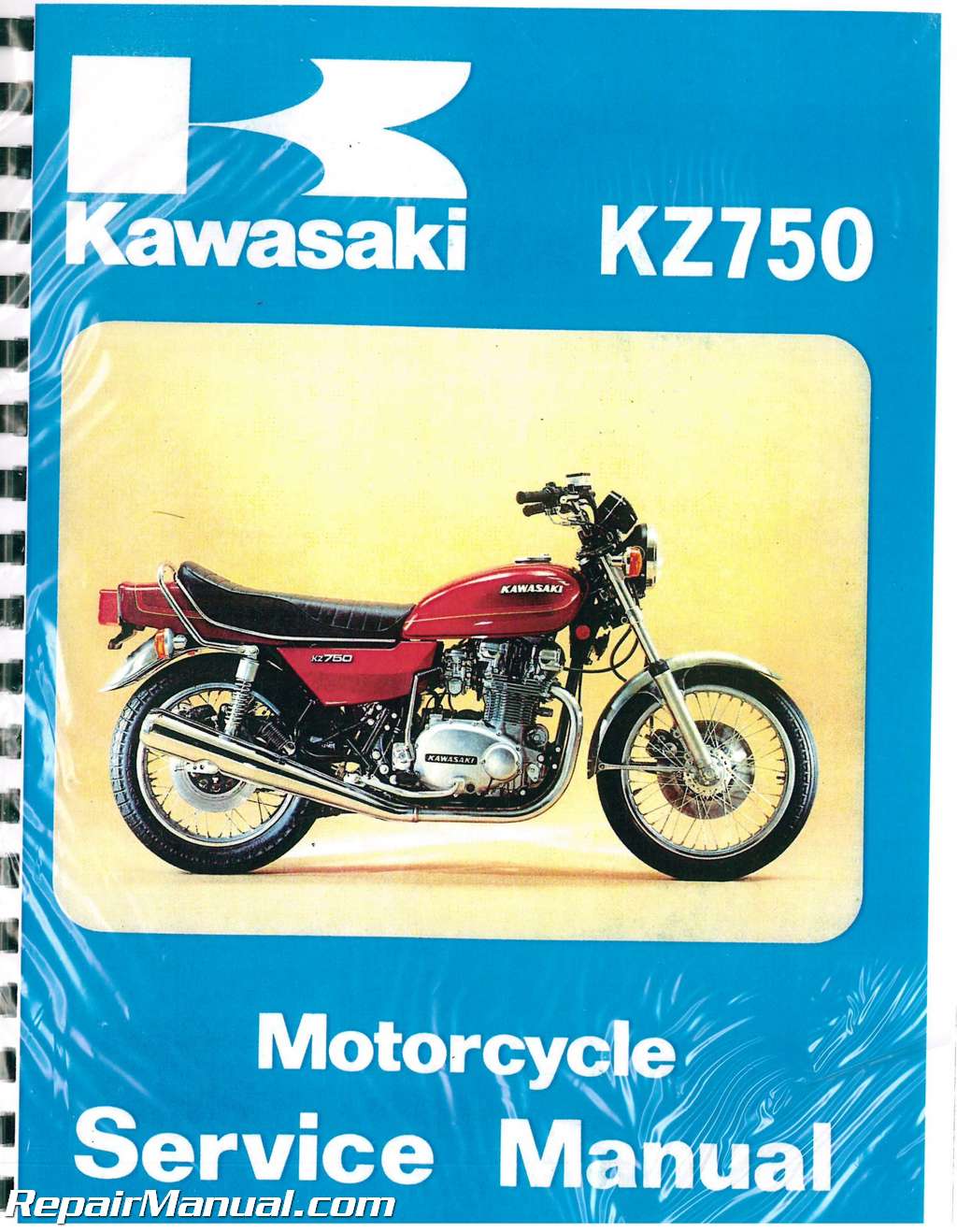
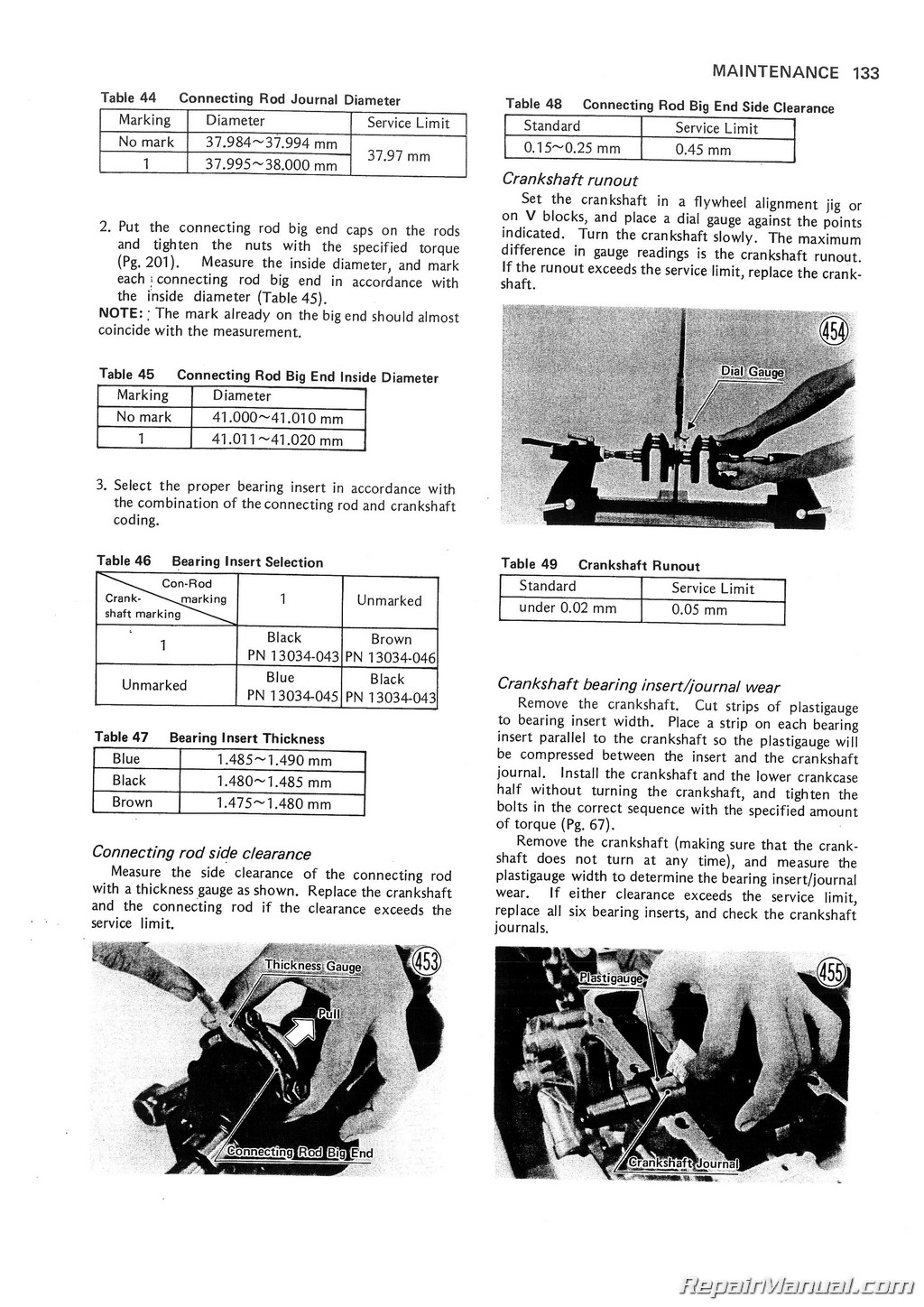
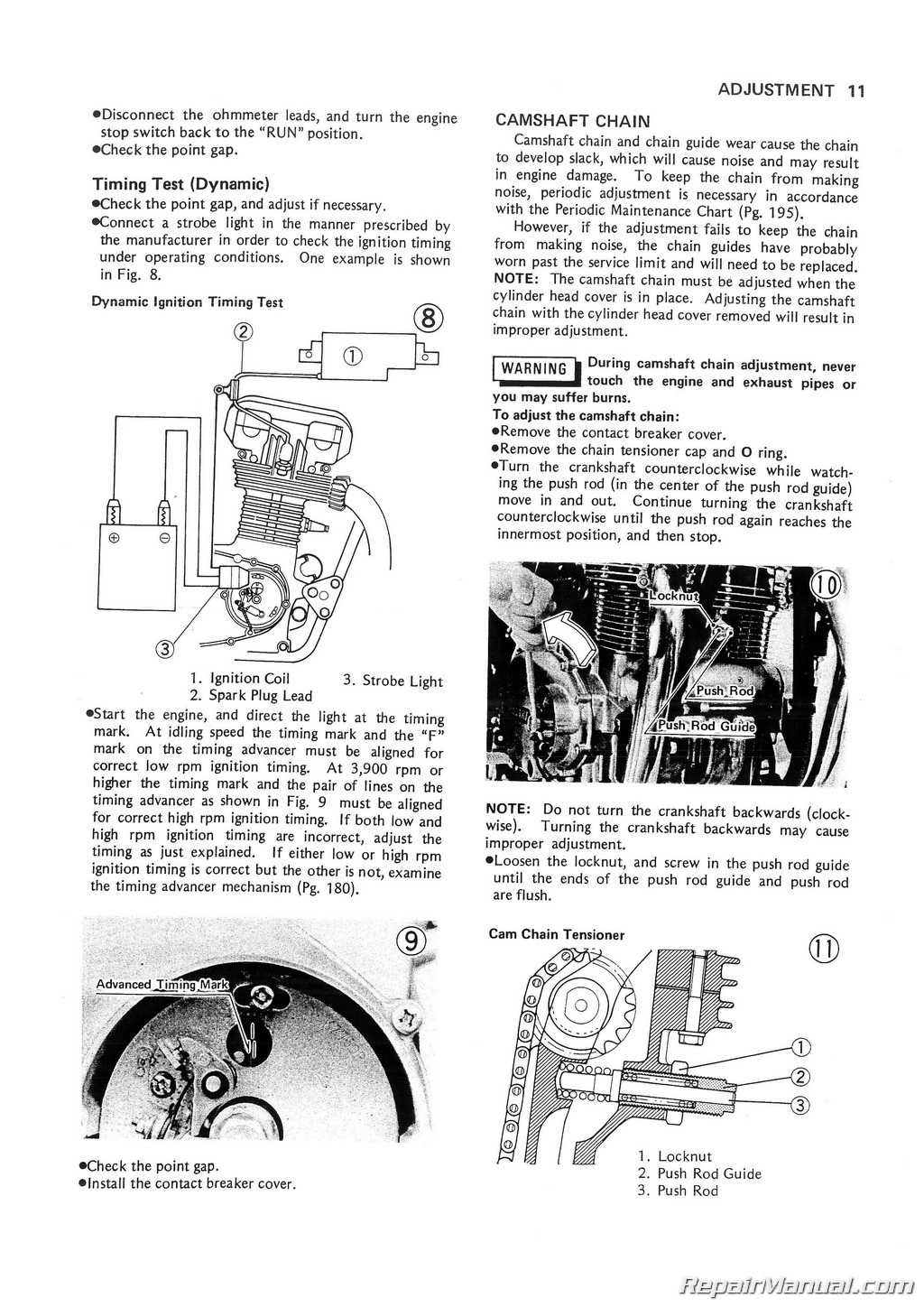
This 237 page, 1976 1977 1978 1979 Kawasaki KZ750 B Service Manual is a reproduction of the original out of print manual. This printed manual provides detailed service information, step-by-step repair instruction, maintenance specifications and wiring diagrams for 1976-1979 Kawasaki KZ750 B Twin cylinder motorcycles.
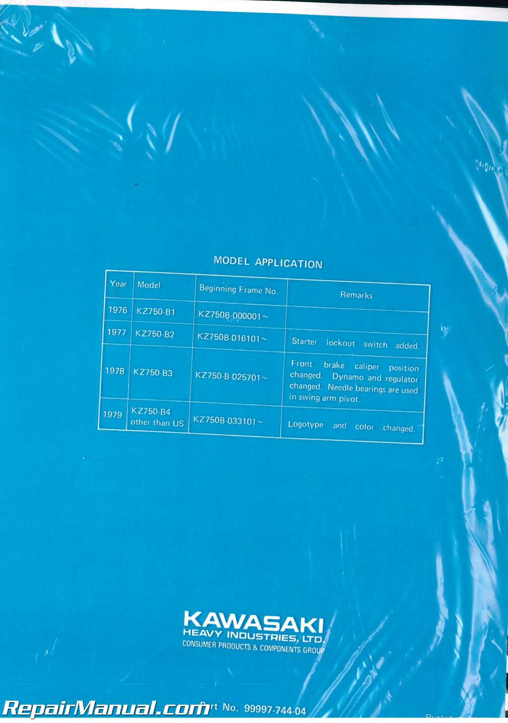
The first issue of this Kawasaki service manual was based on the 1976 Kawasaki KZ750. Since the first issue, certain design changes have been made which require a new disassembly or maintenance procedure. These new procedures which can not be included in each section are explained in an included supplement.
This Kawasaki KZ750 manual is designed primarily for use by motorcycle mechanics in a properly equipped shop, although it contains enough detail and basic information to make it useful to the Kawasaki KZ750 owner who wants to carry out his own basic maintenance and repair work. Since a certain basic knowledge of motorcycle mechanics, the proper use of tools, and workshop procedures must be understood in order to carry out maintenance and repair satisfactorily; the adjustments, maintenance, and repair should be carried out only by qualified mechanics whenever the owner has insufficient experience, or has doubts as to his ability to do the work, so that the motorcycle can be operated safely. In order to perform the work efficiently and to avoid costly mistakes, the mechanic should read the text, thoroughly familiarizing himself with the procedures before starting work, and then do the work carefully in a clean area. Whenever special tools or equipment is specified, makeshift tools or equipment should not be used. Precision measurements can only be made if the proper instruments are used, and the use of substitute tools may adversely affect safe operation of the motorcycle. Purchasing this manual and reading it will always allow you to follow safe operating and maintenance practices.
Table of Contents
Forward
Kawasaki KZ750 Model identification
Kawasaki KZ750 Specifications
Engine performance curves
Running performance curves
Adjustment
Spark plugs
Ignition timing
Camshaft chain
Valve clearance
Throttle cables
Kawasaki KZ750 Carburetors
Clutch
Rear shock absorbers
Drive chain
Brakes
Brake light switch
Steering
Wheel balance
Headlight
Horn
Disassembly
Introduction to disassembly
Engine
Air cleaner element
Oil filter
Muffler
Fuel tank
Carburetors
Camshaft
Camshaft sprocket
Cylinder head
Valves and valve guides
Cylinder block
Piston and piston rings
Dynamo filed coil
And armature
Dynamo rotor (flywheel) and starter motor clutch
Starter motor chain
And sprockets
Starter motor
Ignition coil
Contact breaker
Capacitor
Timing advancer
Clutch hub and clutch plates
Clutch release
Engine sprocket
Neutral indicator switch
External shift mechanism
Kickstarter spring
Breather cover
Engine oil pump
Transmission
Kickstarter
Oil pressure relief valve
Balancer mechanism
Crankshaft, camshaft chain,
And primary chain
Connecting rod
Camshaft chain guide (front)
Camshaft chain guide (rear)
Camshaft chain guide (top)
Front wheel
Front disc brake
Rear wheel
Rear disc brake
Tire and tube
Rim
Spoke
Clutch cable
Throttle cables
Handlebar
Speedometer cable
Tachometer cable
Headlight unit
Speedometer, tachometer, and illuminator lights
Indicator lights
Ignition switch
Turn signal light
Turn signal assembly
Tail/brake light
Oil pressure indicator switch
Front brake light switch
Front fork
Steering stem
Steering stem bearing
Rear shock absorbers
Swing arm
Drive chain
Maintenance & theory of operation
Air cleaner
Carburetors
Camshafts
Camshaft chain, guides,
Tensioner
Cylinder head, valves
Cylinder block and pistons
Crankshaft and connecting rods
Balancer mechanism
Clutch
Primary chain
Transmission
Kickstarter
Engine lubrication
Engine oil seals
Fuel tank
Wheels
Tires
Rim and spokes
Axle
Grease seals and wheel bearings
Rear wheel coupling
Drive chain
Sprockets
Disc brakes
Steering stem
Front fork
Rear shock absorbers
Swing arm
Mufflers
Torque and locking agent
Troubleshooting guide
Flow chart for disassembly
Wiring diagrams
Supplement
Disassembly
Front disc brake
Pad removal and installation (1978 and later models)
Master cylinder disassembly and assembly (1978 and later models)
Transmission
Output shaft (1978 and later models)
Maintenance
Engine lubrication
Relief valve (ball type)
Disc brakes (’78 and later models)
Front fork (’78 and later models)
Charging system (’78 and later models)
Dynamo
Regulator/rectifier
Ignition switch (’78 and later model)
Wiring diagrams
Index
Dynamo (’76 and ’77 models)
Rectifier (’76 and ’77 models)
Regulator (’76 and ’77 models)
Battery
Ignition system
Timing advancer
Spark plugs
Starter motor circuit
Starter motor clutch, chain
Ignition switch
Headlight circuit
Brake light circuit
Turn signals
Horn
Speedometer, tachometer
Appendix
Special tools
Periodic maintenance
Valve adjustment chart
Valve installed height
Procedure table


 SKU: M240-2
 SKU: M354-3
 SKU: U99924-1371-01

