Description
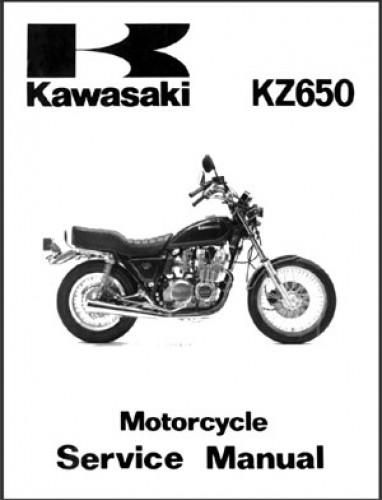
This 220+ page 1981 Kawasaki KZ650 motorcycle service manual provides detailed service information, step-by-step repair instruction and maintenance specifications for 1981 KZ650 D4, F2, & H1 motorcycles. This KZ650 repair manual contains complete information on servicing your motorcycle including wiring diagrams, special tools and troubleshooting information.
High quality reproduction of original, out of print manual.
1981 Kawasaki KZ650 Service Manual Table of Contents
General Information: Before Servicing, Model Identifications, Specifications, Service Data, Torque And Locking Agent, Special Tools, Wiring Diagrams
Scheduled Maintenance: Periodic Maintenance Chart, Sparkplugs, Ignition System, Valve Clearance, Air Suction Valves, Air Cleaner, Throttle Glip, Carburetors, Clutch, Drive Chain, Brakes, Brake Light Switches, Steering, Front Fork, Swing Arm, Battery, Fuel System, General Lubrication, Bolt And Nut Tightening
Non-Scheduled Maintenance-Engine: Fuel Tank, Fuel Tap, Tank Cap, Carburetors, Vacuum Switch Valve, Camshafts, Chain, Guides, Tensioner Cylinder Head, Cylinder Block, Pistons, Crankshaft, Connecting Rods, Primary Chain, Sprockets, Clutch, Engine Lubrication, Ball Bearings, Needle Bearings, Oil Seals
Non-Scheduled Maintenance – Chassis: Wheels, Drive Train, Brakes, Steering, Suspensions
Non-Scheduled Maintenance-Electrical: Battery, Charging System, Ignition System, Ignition Switch, Electric Starter System, Lighting System, Horn, Low Fuel Warning System
Disassembly – Engine:
Engine Removal – Flow Chart, Fuel Tank, Fuel Tap, Fuel Level Sensor, Ignition Coils, Vacuum Switch Valve, Carburetors, Air Cleaner Element, Air Cleaner Housing, Mufflers, Engine Sprocket Cover, Clutch Release, Engine Sprocket, Engine Unit
Engine Top End – Flowchart, Tachometer Pinion, Camshaft Chain Tensioner, Camshafts, Cylinder Head, Cylinder Block, Pistons, Air Suction Valves, Camshaft Sprockets, Camshaft Chain Guides, Cylinder Head Valves, Carburetor Holders, Piston Rings, Breather Cover
Engine Left Side – Flow Chart, Alternator Rotor, Alternator Stator, Starter Motor, Neutral Switch, External Shift Mechanism
Engine Right Side – Flowchart, Pickup Coil Assy, Timing Advancer, Oil Pressure Switch, Clutch
Engine Buttom End – Flow Chart, Oil Filter, Oil Pressure Relief Valve, Oil Pump, Secondary Shaft, Secondary Sprocket And, Starter Motor Clutch, Starter Motor Idle Gear Oil Filter Bypass Valve
Engine Split – Flow Chart, Drive Shaft, Output Shaft, Crankshaft, Primary Chain Camshaft Chain Connecting Rods, Shift Mechanism
Disassembly – Chassis:
Wheels – Flowchart, Front Wheel, Speedometer Gear, Rear Wheel, Grease Seals, Wheel Bearings, Tubes, Tires, Rims, Spokes , Tubeless Tires, Cast Rims, Air Valves
Drive Train – Flow Chart, Drive Chain, Sprockets, Rear Wheel Coupling, Rubber Damper
Brakes – Flow Chart, Discs, Pads, Calipers, Front Master Cylinder, Rear Master Cylinder, Rear Master Cylinder Reservoir, Brake Hoses, Rear Drum Brake
Steering – Flowchart, Handlebar, Steering Stem, Steering Stem Bearings
Suspension – Flow Chart, Front Fork, Rear Shock Absorbers, Swing Arm
Appendix: Troubleshooting Guide, Additional Considerations For Racing Unit Conversion Table.


 SKU: M354-3
 SKU: M241
 SKU: 99920-1326-01

