Description
This 173 page, 1982 Yamaha XT550 Motorcycle Service Manual is a reproduction of the original out of print manual. If you are looking for a collectible original this is NOT it. However if you need repair information, this book provides detailed service information, step-by-step repair instruction and maintenance specifications for 1982 Yamaha XT550J motorcycles. Book is comb bound with a sturdy plastic binder that allows the book to lay flat, there is no spine to crack or pages to fall out like in a perfect bound book.
Table of Contents
General Information
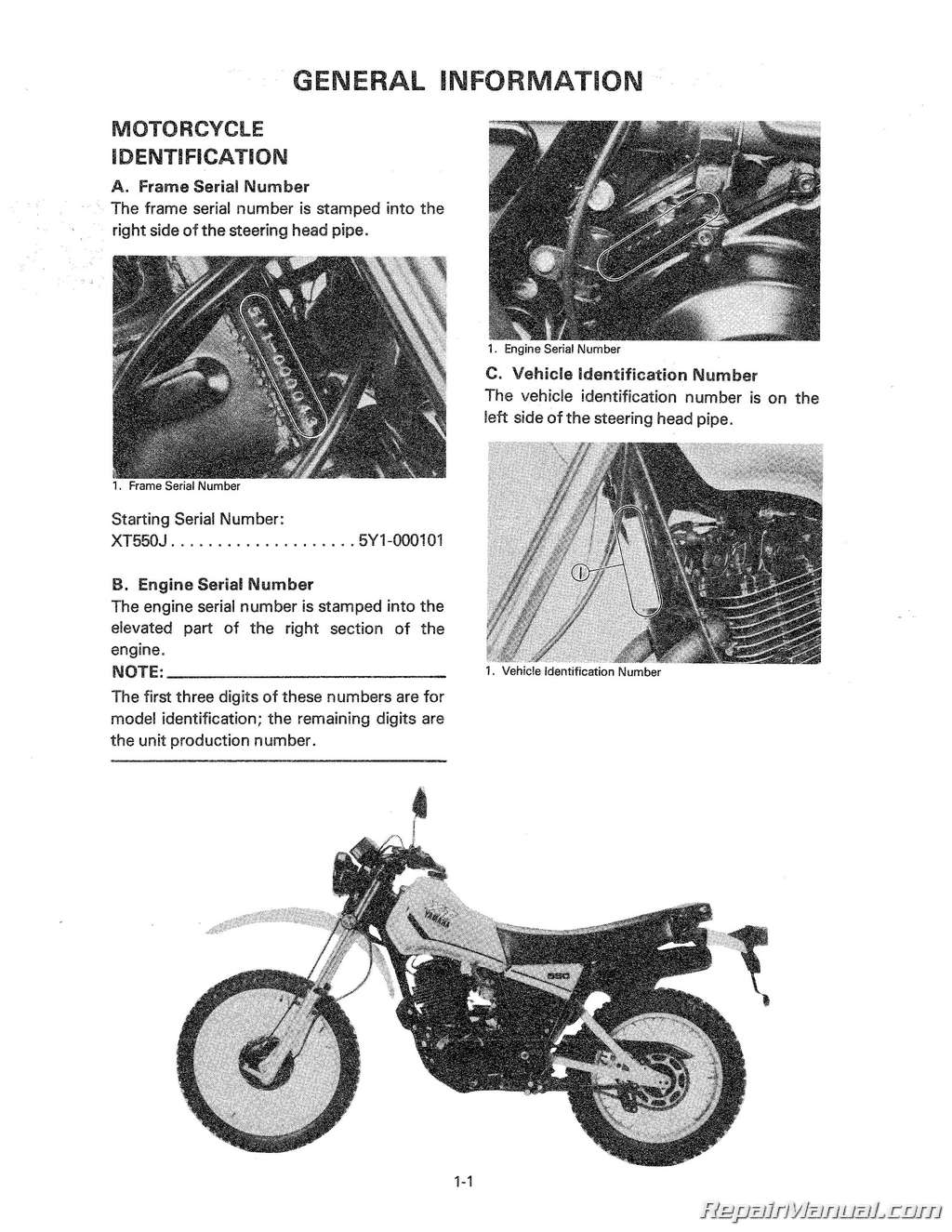
MOTORCYCLE IDENTIFICATION
A Frame Serial Number
B Engine Serial Number
C Vehicle Identification Number
MAIN FEATURES
A Dry Sump System and Monocross Suspension
B Four-Valve Engine
C Yamaha Duo Intake System (YDIS)
D Kick Synchronous Automatic Decompression
E DC Lighting System
F Detachable Lighting System
G Fuel Tank Cap with Check Valve
SPECIAL TOOLS
A For Tune-up
B For Engine Service
C For Chassis Service
D For Electrical Components
Periodic Inspections and Adjustments
INTRODUCTION
MAINTENANCE INTERVALS CHARTS
ENGINE
A Valve Clearance
B Decompression System
C Spark Plug
D Crankcase Ventilation System
E Fuel Line
F Exhaust System
G Idle Speed
H Engine Oil
I Oil Filter Replacement
J Engine Oil Replacement
K Oil Pressure Check
L Clutch Adjustment
M Checking Ignition Timing
N Compression Pressure Measurement
CHASSIS
A Down Tube Strainer
B Air Filter
C Front and Rear Brake
D Cable Inspection and Lubrication
E Brake and Change Pedals/ Brake and Clutch Levers/ Sidestand
F Drive Chain
G Front Fork Oil Change
H Front Fork and Rear Shock Absorber Adjustment
I Steering Head Adjustment
J Wheel Bearings
K Fuel Cock
L Tires and Wheels
ELECTRICAL
A Battery
B Circuit Breaker
Engine Overhaul
ENGINE REMOVAL
A Preparation for Removal
B Seat and Fuel Tank
C Muffler, Footrest, and Brake Pedal
D Oil Hoses
E Carburetor
F Drive Chain and Drive Sprocket
G Engine Mounting Bolts
DISASSEMBLY
A Cylinder Head Cover
B Cylinder Head
C Cylinder
D Piston Pin and Piston
E Kick Crank
F CDI Rotor
G Cam Chain and Guide Stopper
H Crankcase Cover (Right)
I Clutch Assembly and Drive Gear
J Clutch Push Lever Axle
K Oil Pump Assembly
L Kick Axle Assembly
M Change Shaft Assembly
N Balancer Gear
0 Crankcase
P Transmission
Q Crankshaft
R Oil Strainer Assembly
INSPECTION AND REPAIRING
A Cylinder Head Cover
B Cylinder Head
C Valves, Valve Guides, Valve Seats, and Valve Springs
D Rocker Arms and Rocker Arm Shafts
E Camshafts, Cam Chains, and Cam Sprockets
F Cylinder
G Piston and Piston Rings
H Crankshaft and Connecting Rod
1 Oil Pump
J Primary Drive
K Clutch
L Transmission
M Kick Starter
N Bearings and Oil Seals
0 Installation
ENGINE ASSEMBLY AND ADJUSTMENT
A Important Information
B Left-Side Crankcase
C Crankshaft Installation
D Oil Pump
E Shifter
F Kick Starter
G Balancer Drive Gear and Driven Gear
H Push Lever Assembly
I Primary Gears and Dutch
J Clutch
K Clutch Mechanical Adjustment
L Crankcase Cover Right
M Kick Crank Assembly
N Piston and Piston Ring
0 Cylinder
P CYlinder Head, Rocker Arm, and Camshaft
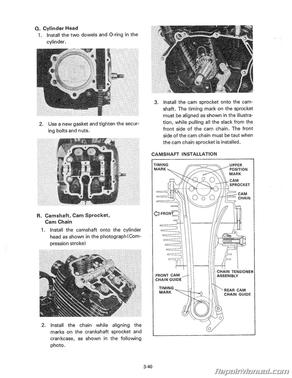
Q Cylinder Head
R Cam Shaft, Cam Sprocket, Cam Chain
S Cam Chain Tensioner
T Cylinder Head Cover
U Flywheel
V Crankcase Cover1
W Decompression Cable
X Drive Sprocket
Y Oil Delivery Pipe
Z Drain Plug
ENGINE MOUNTING
Carburetion
CARBURETOR
A Section View
B Specifications
C Disassembly
D Inspection
E Assembly
F Adjustment
AIR CLEANER AND CRANKCASE VENTILATION SYSTEM
Chassis
FRONT WHEEL
A Removal
B Checking Brake Shoe Wear
C Brake Drum
D Brake Shoe Plate
E Front Axle Inspection
F Replacing Wheel Bearings
G Front Wheel Inspection
H Installing Front Wheel
REAR WHEEL
A Removal
B Checking Brake Shoe Wear
C Brake Drum
D Brake Shoe Plate
E Rear Axle Inspection
F Replacing Wheel Bearings
G Rear Wheel Inspection
H Installing Rear Wheel
RIMS AND SPOKES
A Checking for Loose Spokes
B Checking Rim “Run-Out”
TIRES AND TUBES
A Removal
B Installation
DRIVE CHAIN AND SPROCKETS
A Drive Sprocket
B Driven Sprocket
C Chain Inspection
D Chain Maintenance
FRONT FORK
A Removal and Disassembly
B Inspection
C Assembly
STEERING HEAD
A Adjustment
B Removal
C Inspection
D Assembly
SWINGARM
A Free Play Inspection
B Removal
C Inspection and Lubrication
D Assembly
REAR SHOCK ABSORBER
A Removal
B Inspection
C Installation and Adjustment
CABLES AND FITTINGS
A Cable Maintenance
B Throttle Maintenance
C Lubrication of Levers, Pedals, etc
Electrical
ELECTRICAL COMPONENTS
XT550J WIRING DIAGRAM
CHARGING SYSTEM
AC GENERATOR AND VOLTAGE REGULATOR
A Inspection
B Battery Inspection
C Stator Coil Inspection
IGNITION SYSTEM
A Description
B Ignition Timing ,
C C D I Unit Test
D C D I Unit Test by Yamaha Pocket Tester
E Troubleshooting
LIGHTING SYSTEM
A Easy-maintenance Lighting System
B Lighting Tests and Checks
SIGNAL SYSTEM
A Signal System Tests and Checks
B Switches
C Battery


 SKU: M489-2
 SKU: M495-7
 SKU: M282-2

