Description
This Official 2005-2006 Honda PS250 Big Ruckus Factory Service Manual provides detailed service information, step-by-step repair instruction and maintenance specifications for 2005-2006 Honda PS250 Big Ruckus scooters.
This 2005-2006 Honda PS250 Big Ruckus Factory Service Manual is the factory issued service guide. This manual is Honda’s reproduction of the original publication printed by Honda. The quality of the photos is not up to Honda’s normal standard.
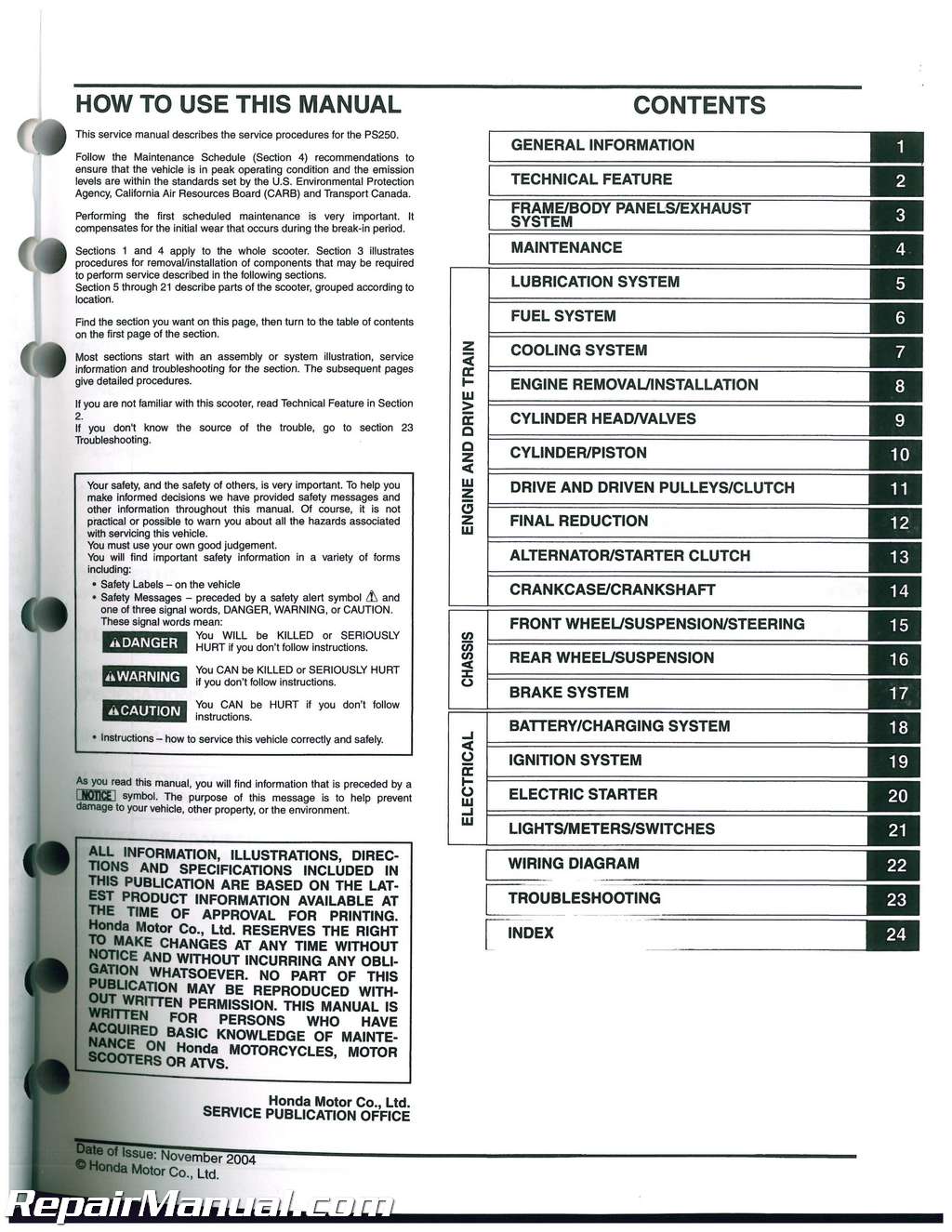
Table of Contents
General Information
Technical Feature
Frame/body Panels/exhaust System
Maintenance
Lubrication System
Fuel System
Cooling System
Engine Removal/installation
Cylinder Head/valves
Cylinder/piston
Drive And Driven Pulleys/clutch
Final Reduction
Alternator/starter Clutch
Crankcase/crankshaft
Front Wheel/suspension/steering
Rear Wheel/suspension
Brake System
Battery/charging System
Ignition System
Electric Starter
Lights/meters/switches
Wiring Diagram
Troubleshooting
Index
Index of Topics
Air Cleaner
Air Cleaner Housing
Alternator Charging Coil
Battery
Bearing Replacement
Belt Case Air Cleaner
Body Panel Locations
Brake Caliper
Brake Fluid
Brake Fluid Replacement/air Bleeding
Brake Light Switch
Lights/m Eters/s Witch Es
Maintenance
Brake Lock Operation
Brake Pad/disc
Brake Shoe/pad Wear
Brake System
Brake/ta1llight
Cable & Harness Routing
Camshaft Installation
Camshaft Removal
Carburetor Assembly
Carburetor Disassembly
Carburetor Installation
Carburetor Removal
Center Cover
Centerstand
Charging System Inspection
Clutch/driven Pulley
Component Location
Battery/charging System
Electric Starter
Ignition System
Lights/meters/switches
Coolant Replacement
Coolant Temperature Indicator/instrument Ect Sensor
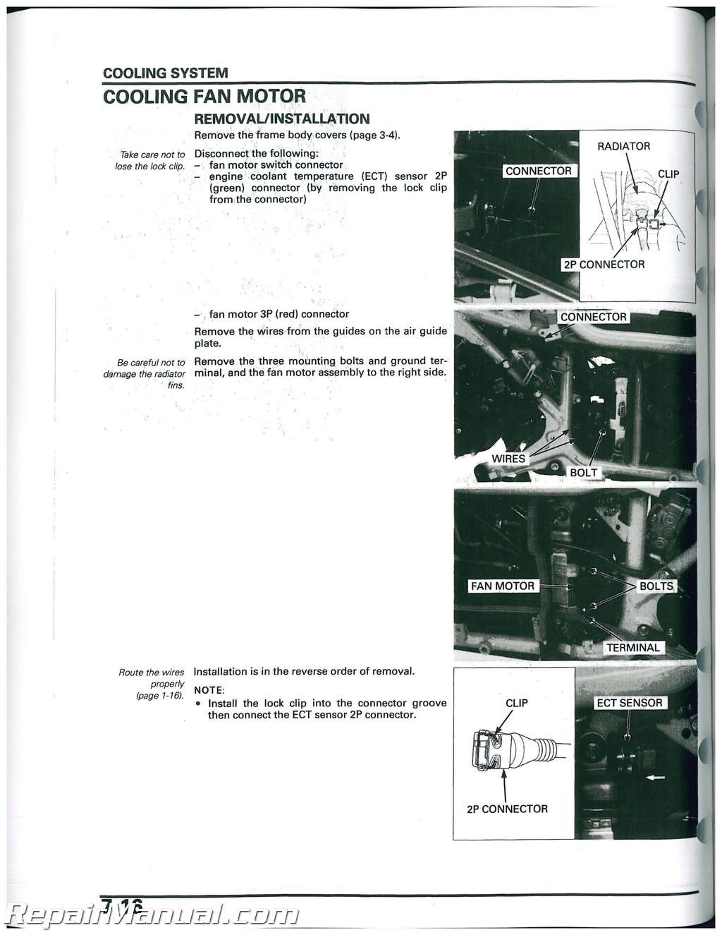
Cooling Fan Motor
Cooling System
Cooling System Flow Pattern
Cooling System Testing
Crankcase Breather
Crankcase/crankshaft
Cylinder Compression Test
Cylinder Head Assembly
Cylinder Head Cover Installation
Cylinder Head Cover Removal
Cylinder Head Disassembly
Cylinder Head Installation
Cylinder Head Removal
Cylinder/piston Inspection
Cylinder/piston Removal
Delay Valve
Drive Belt
Drive Pulley
Emission Control Information Labels
Emission Control Systems
Engine Coolant Temperature (ect) Sensor
Engine Hanger Bracket
Engine Idle Speed
Engine Installation
Engine Oil
Engine Oil Strainer Screen
Engine Removal
Evaporative Emission Control System (usa Only)
Fuel System
Maintenance
Exhaust System
Fan Motor Switch
Final Drive Oil
Final Reduction Assembly
Final Reduction Disassembly/inspection
Flywheel Installation
Flywheel Removal
Fork
Frame Body Cover
Front Cover
Front Fender
Front Lower Cover
Front Master Cylinder
Front Wheel
Fuel Gauge/fuel Level Sensor
Fuel Line
Fuel Pump
Fuel Tank
Handlebar
Handlebar Switch
Headlight
Headlight Aim
Headlight Relay
High Altitude Adjustment
Horn
Ignition Coil
Ignition Control Module (icm)
Ignition Switch
Ignition System Inspection
Ignition Timing
Inner Box
Inner Box Cover
Left Crankcase Cover
Lubrication & Seal Points
Lubrication System Diagram
Luggage Box
Maintenance Schedule
Model Identification
Nuts, Bolts, Fasteners
Oil Pump
Parking Brake Indicator Switch
Parking Brake Lever
Pilot Screw Adjustment
Piston Ring Installation
Piston/cylinder Installation
Radiator
Radiator Coolant
Radiator Reserve Tank
Rear Deck Panel
Rear Drum Brake
Rear Fender
Rear Master Cylinder
Rear Shock Absorber
Rear Wheel
Regulator/rectifier
Right Crankcase Cover Installation
Right Crankcase Cover Removal
Seat
Seat Frame Assembly
Secondary Air Supply System
Fuel System
Maintenance
Service Information
Alternator/starter Clutch
Battery/charging System
Brake System
Cooling System
Crankcase/crankshaft
Cylinder Head/valves
Cylinder/piston
Drive Pulley/driven Pulley/clutch
Electric Starter
Engine Removal/installation
Final Reduction
Frame/body Panels/exhaust System
Front Wheel/suspension/steering
Fuel System
Ignition System
Lights/meters/switches
Lubrication System
Maintenance
Rear Wheel/suspension
Service Rules
Side Cover
Side Stand
Frame/body Panels/exhaust System
Maintenance
Side Stand Switch
Skid Plate
Sparkplug
Specifications
Alternator/starter Clutch
Battery/charging System
Brake System
Cooling System
Crankcase/crankshaft
Cylinder Heada/alves
Cylinder/piston
Drive And Driven Pulleys/clutch
Electric Starter
Final Reduction
Front Wheel/suspension/steering
Fuel System
General
Ignition System
Lights/meters/switches
Lubrication System
Rear Wheel/suspension
Speedometer
Starter Clutch
Starter Inhibitor Switch
Starter Motor
Starter Relay Switch
Stator/ignition Pulse Generator
Steering Head Bearings
Steering Stem
Suspension
System Components
Alternator/starter Clutch
Brake System
Crankcase/crankshaft
Cylinder Heada/alves
Cylinder/piston
Drive Pulley/driven Pulley/clutch
Engine Removal/installation
Final Reduction
Front Wheel/suspension/steering
Fuel System
Rear Wheel/suspension
System Diagram
Battery/charging System
Electric Starter
Ignition System
Technical Feature
(combined Brake System)
Thermostat
Throttle Operation
Throttle Position (tp) Sensor
Thrust Cylinder
Torque Values
Engine & Frame
Standard
Troubleshooting
Alternator/starter Clutch
Battery/charging System
Brake System
Cooling System
Crankcase/crankshaft
Cylinder Heada/alves
Cylinder/piston
Drive Pulley/driven Pulley/clutch
Electric Starter
Engine Does Not Start Or Is Hard To
Start
Engine Lacks Power
Final Reduction
Frame/body Panels/exhaust System
Front Wheel/suspension/steering
Fuel System
Ignition System
Lubrication System
Poor Performance At High Speed
Poor Performance At Low And Idle
Speed
Rear Wheel/suspension
Turn Signal Light
Turn Signal Relay
Valve Clearance
Valve Guide Replacement
Valve Seat Inspection/refacing
Water Pump
Wheels/tires
Wiring Diagram

 SKU: M440
 SKU: M457-2
 SKU: M322
