Description
This Official 2006 Polaris Sportsman 500 EFI Factory Service Repair Manual provides detailed service information, step-by-step repair instruction and maintenance specifications for 2006 Polaris Sportsman 500 EFI ATVs.
Service Repair Manual Table of Contents
Chapter 1: General
Chapter 2: Maintenance
Chapter 3: Engine
Chapter 4: Fuel Injection
Chapter 5: Body And Steering
Chapter 6: Clutching
Chapter 7: Final Drive
Chapter 8: Transmission
Chapter 9: Brakes
Chapter 10: Electrical
Service Repair Manual Index of Topics
CHAPTER 1 – GENERAL
Model Identification
Serial Number Location
Publication Numbers
Paint Codes
Replacement Keys
General Specifications – Sportsman 500
Special Tools
Standard Torque Specifications
Decimal Equivalent Chart
Conversion Table
Glossary of Terms
CHAPTER 2 – MAINTENANCE
Periodic Maintenance Chart
Lubricant and Maintenance Product Numbers
ATV Component Locations
Lubrication Charts
Front Gearcase Lubrication
Transmission Lubrication
Lubrications Points
Transmission Linkage Adjustment
Carburetor / Throttle Adjustments
Fuel System
Compression Test
Battery Maintenance
Coolant System Maintenance
Air Filter Service
Air Box Sediment Tube Service
Breather Filter
Recoil Housing
Oil Change/Filter
Valve Clearance
Steering and Toe Alignment
Exhaust System Maintenance
Brake System Service
Suspension Service
Controls
Wheel Removal/Installation
Tire Inspection
Compartment Storage
Warn™ Winch Operation
Cleaning and Storage of ATV
CHAPTER 3 -ENGINE
Torque Specifications
Special Tools
EH50PL Service Data
Torque Patterns
Piston Identification
Cooling System Pressure Test
Cooling System Specifications
Engine Removal
Engine Installation Notes
Cylinder Honing
Crankshaft Runout Inspection
EH50PL Engine Lubrication
EH50PL Oil Pump Priming Procedure
EH50PL Lubrication/Oil Flow
EH50PL Engine Exploded View
EH50PL Engine Top End Disassembly
EH50PL Valve Seat Service
EH50PL Cylinder Head Assembly
EH50PL Engine Bottom End Disassembly
EH50PL Crankcase & Bearing Assembly
EH50PL Crankshaft End Play Inspection
EH50PL Counter Balancer End Play Inspection
EH50PL Oil Pump Shaft End Play Inspection
EH50PL Engine Assembly/Inspection
Sealed Recoil Disassembly/Inspection
Sealed Recoil Assembly
Spark Plug Fouling Checklist
Troubleshooting
CHAPTER 4 – FUEL INJECTION
SPECIAL TOOLS
Part Numbers / Descriptions
EFI SERVICE NOTES
General Service Information
EFI SYSTEM EXPLODED VIEW EFI SYSTEM
Component Locations/Identification
FUEL TANK
Exploded View
ELECTRONIC FUEL INJECTION
General Information
EFI OPERATION OVERVIEW INITIAL PRIMING / STARTING PROCEDURE FUEL LINES
Quick Connect Removal/Installation
ELECTRONIC CONTROL MODULE (ECM)
Operation Overview
ECM REPLACEMENT ECM SERVICE FUEL PUMP ASSEMBLY
Operation / Testing
FUEL PUMP TEST
FUEL PUMP / TANK ASSEMBLY REPLACEMENT FUEL PRESSURE REGULATOR FUEL FILTERS FUEL INJECTOR
CRANKSHAFT POSITION SENSOR (CPS)
MANIFOLD AIR PRESSURE SENSOR (MAP)
Map Sensor Test
Map Sensor Replacement
INTAKE AIR TEMPERATURE SENSOR (IAT)
Intake Air Temperature Sensor
Test Intake Air Temperature Sensor Replacement
IDLE AIR CONTROL (IAC)
THROTTLE POSITION SENSOR (TPS)
Throttle Position Sensor Test
Throttle Position Sensor Replacement
hrottle Position Sensor (tps) Initialization
ENGINE TEMPERATURE SENSOR
Engine Temperature Sensor Test
Engine Temperature Sensor Replacement
Fuel System Troubleshooting
DIAGNOSTICS USING BLINK CODES
Blink Codes – Operation
TROUBLESHOOTING DIAGRAMS
EFI CIRCUIT – Power On
EFI CIRCUIT – Fuel Injector
EFI CIRCUIT – Fuel Pump
EFI CIRCUIT – Ignition Coil
EFI CIRCUIT – Idle Air Control
EFI CIRCUIT – Throttle Position Sensor
EFI CIRCUIT – Manifold Absolute Pressure Sensor
EFI CIRCUIT – Engine Coolant Temperature
EFI CIRCUIT – Air Temperature Sensor
EFI CIRCUIT – Malfunction Indicator Light
CHAPTER 5 – BODY AND STEERING
Torque Specifications and Special Tools
Plastic Insert Removal/Install
Side Panel Removal
Front Cover Removal
Foot Well Removal/Install
Front Storage Removal/Install
Rear Rack Remove/Install
Front Cab / Fender Remove/Install
Rear Cab/ Fender Remove/Install
Radiator Screen Removal
Body Assembly, Exploded View
Headlight Pod Exploded View
Handlebar Block Installation
Steering Assembly, Exploded View
A-Arm Replacement
Rear Suspension Assembly
Strut Assembly Exploded View
Front Strut Cartridge Replacement
Front Strut Ball Joint Replacement
Steering Post Assembly
Decal Replacement
CHAPTER 6 – CLUTCHING
Service Tools, Supplies & Torques
PVT System Operation
PVT Maintenance/Inspection
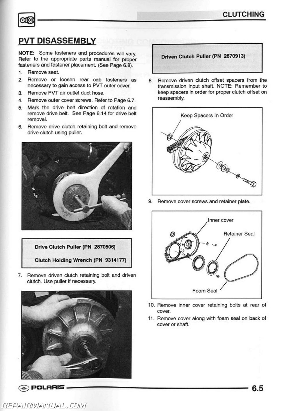
PVT Disassembly
PVT Assembly
PVT Sealing and Ducting Components
Drive Clutch Exploded View
Drive Clutch Spring Specifications
Shift Weights
Drive Clutch Inspection
Drive Clutch Disassembly
Drive Clutch Assembly
Drive Belt Tension
Drive Belt Removal/Inspection
Drive Belt Installation
Clutch Alignment /Offset
Drive Clutch Bushing Service
Driven Clutch Disassembly/Inspection
Driven Clutch Assembly
Driven Clutch Bushing Service
EBS Exploded View
EBS Drive Clutch Disassembly/Inspection
EBS Drive Clutch Bushing Service
EBS Driven Clutch Disass/lnsp
EBS Driven Clutch Bushing Serv
Troubleshooting
CHAPTER 7 – FINAL DRIVE
Final Drive Torque Specifications
AWD Front Axle Remove/Install
AWD Front CV Joint Boot Replace
AWD Front Drive Axle Exploded View
Front Hub Disass/Assemble
AWD Front Prop Shaft Removal
U-Joint Disassemble/Assemble
Drive Axle / Propshaft Exploded View
AWD Front Gearcase Operation
AWD Front Gearcase Service
Rear Hub Remove/Install
Rear Hub Disassembly/Assembly
Rear Drive Shaft Removal
Driveshaft / CV Joint Tips
Rear Driveshaft Installation
Rear Driveshaft Service
CHAPTER 8 – TRANSMISSION
Transmission Mounting
Torque Specifications
Special Tools
Transmission Removal
Transmission Installation Transmission Disassembly
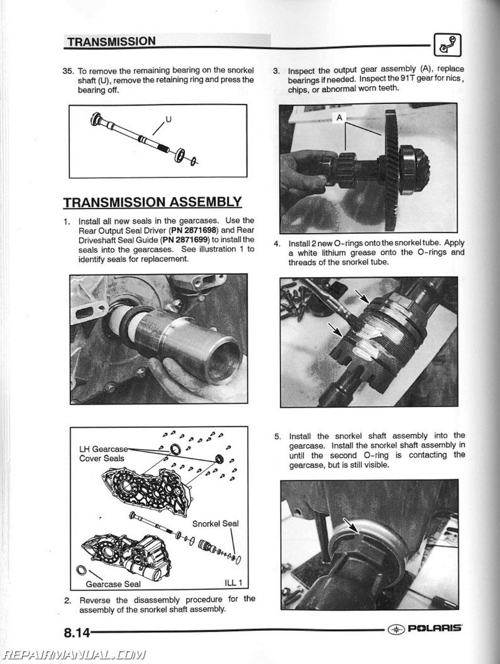
Transmission Assembly
Troubleshooting
Transmission Exploded View
CHAPTER 9 – BRAKES
Special Tools/Specifications/Torques
Brake System Components
Rear Caliper Exploded View
Front Caliper Exploded View
Rear Auxiliary Master Cylinder Exploded View
Brake System Service Notes
Brake Noise Troubleshooting
Hydraulic Brake System Overview
Hydraulic Caliper Bleeding
Brake Bleeding / Fluid Change
Master Cylinder Removal
Master Cylinder Installation
Front Pad Removal
Front Pad Assembly
Brake Burnishing
Front Disc Inspection
Front Disc Removal/Replacement
Front Caliper Removal
Front Caliper Disassembly
Front Caliper Inspection
Front Caliper Reassembly
Front Caliper Installation
Rear Pad Removal
Rear Pad Installation
Rear Caliper Removal/Inspection
Rear Caliper Reassembly
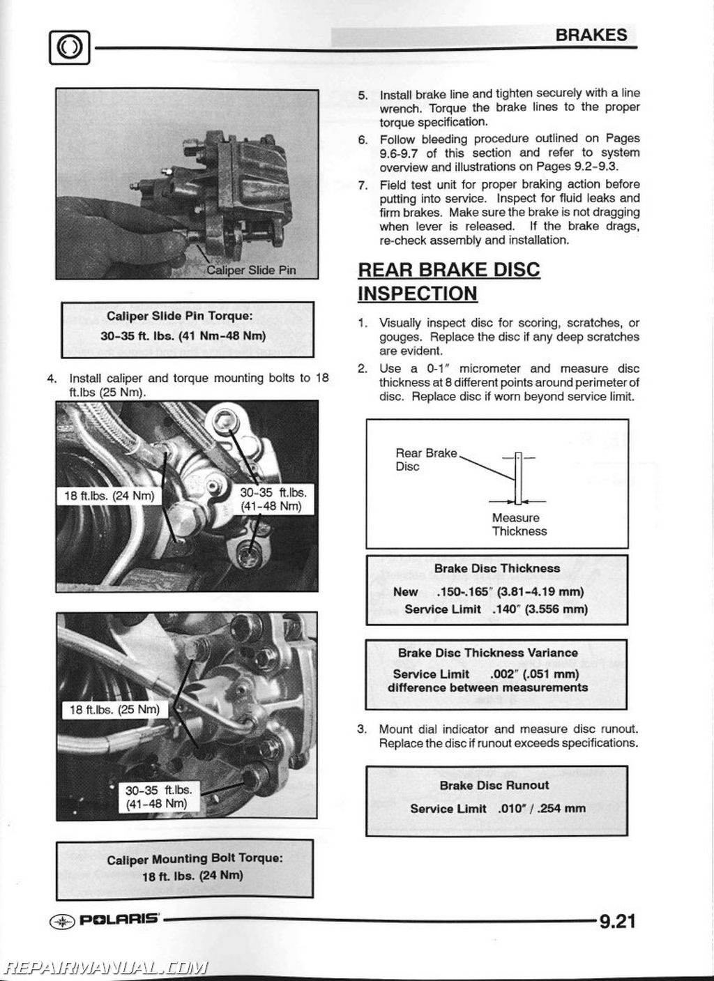
Rear Disc Inspection
Rear (Auxiliary) Brake Remove/Install
Troubleshooting
CHAPTER 10 – ELECTRICAL
Special Tools/ Components
Service Notes / Troubleshooting
Power Distribution Module / Operation
Instrument Cluster Operation
Speedometer Removal/Installation
Speedometer Systems Troubleshooting
Coolant Sensor Test
Fan Motor Tests
Electronic Throttle Circuit (ECT) Operation
Ignition System Information
Charging / Ignition System Exploded View
Ignition System Flow Chart
Charging System Testing
Battery Activation/Service
Head Light/Brake Light Lamp Service
Work light / Brake light Switch
Fuel Sender Test
Accessory Wire Hookup
Warn™ Winch Wiring Schematic
Starter System Troubleshooting
Starter Motor Service
Starter Drive and Assembly Exploded View
Starter System Testing Flow Chart
Electrical Circuit Diagrams


 SKU: 9917198
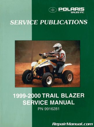 SKU: U9916281
 SKU: 9921434