Description
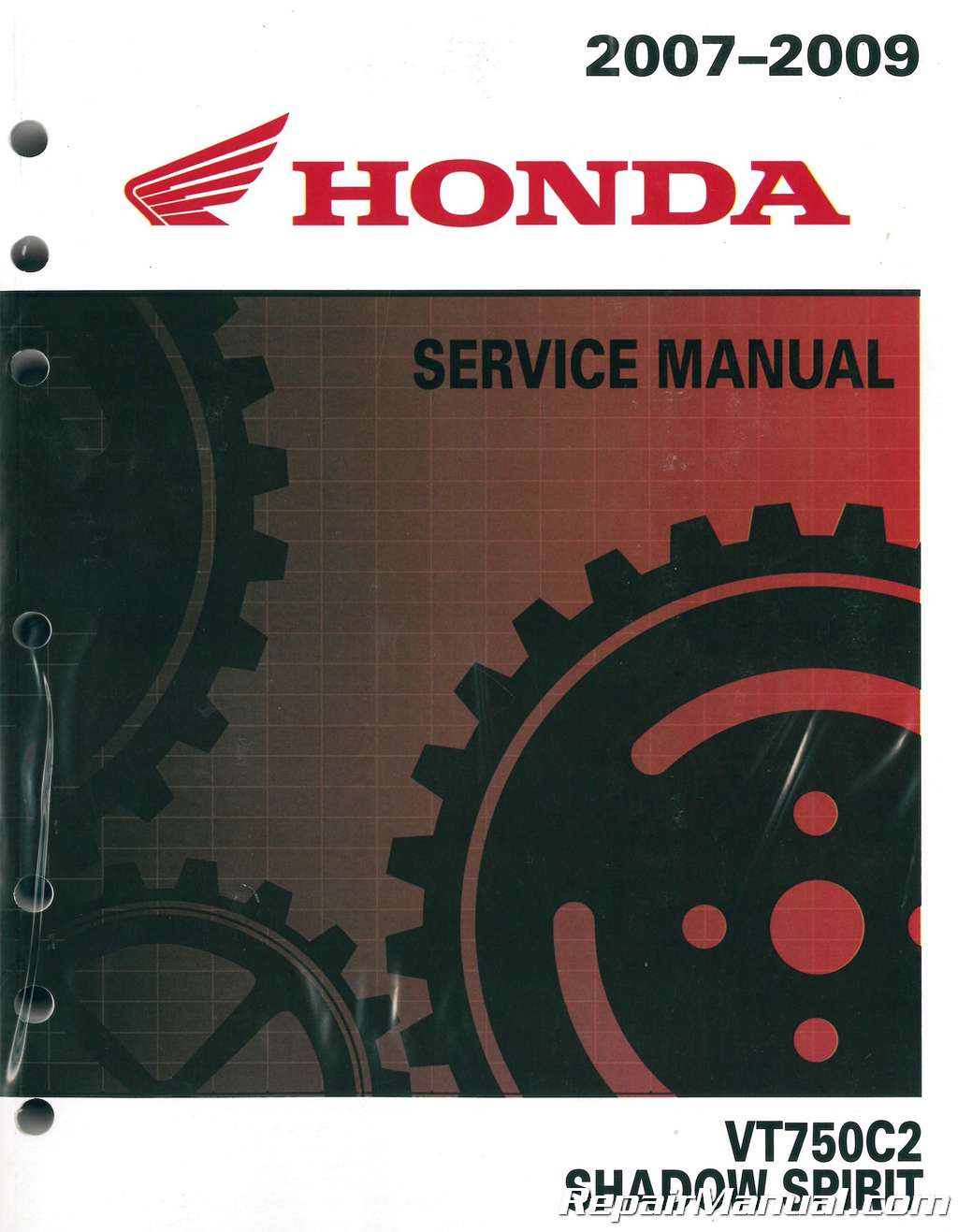
This VT750C2 Service Manual 2007-2009 Honda Shadow Spirit provides detailed service information, step-by-step repair instruction and maintenance specifications for 2007-2009 Honda VT750C2 Shadow Spirit motorcycles.
The service and repair information contained in this Honda VT750C2 Service Manual is intended for use by qualified, professional technicians. It describes the proper methods and procedures for performing service, maintenance, and repairs. Some procedures require the use of specially designed tools and dedicated equipment.
When using this Honda VT750C2 Service Manual to work on Honda VT750C2/C2F motorcycles you will want to follow the Maintenance Schedule (Section 4) recommendations to ensure that the vehicle is in peak operating condition and the emission levels are with the standards set by the U.S. Environmental Protection Agency, California Air Resources Board (CARB) and Transport Canada.
Performing the first scheduled maintenance explained in this VT750C2 Service Manual is very important. It compensates for the initial wear that occurs during the break-in period.
Sections 1 and 4 of this VT750C2 Service Manual apply to the whole motorcycle. Section 3 illustrates procedures for removal/installation of components that may be required to perform service described in the following sections.
Section 5 through 21 of the VT750C2 Service Manual describes parts of the Honda VT750C2, grouped according to component location.
Most sections in this VT750C2 Service Manual start with an assembly or system illustration, service information and troubleshooting for the section. The subsequent pages give detailed procedure. If you need more help see section 23, Troubleshooting.
This VT750C2 Service Manual applies to the following motorcycles:
2007 Honda VT750C2 Shadow Spirit
2008 Honda VT750C2 Shadow Spirit
2009 Honda VT750C2 Shadow Spirit
VT750C2 Service Manual Table Of Contents
General Information
Technical Feature
Frame/body Panels/exhaust System
Maintenance
Lubrication System
Fuel System
Cooling System
Engine Removal/installation
Cylinder Head/valve
Cylinder/piston
Clutch/gearshift Linkage
Alternator/starter Clutch
Crankshaft/transmission
Final Drive
Front Wheel/suspension/steering
Rear Wheel/brake/suspension
Hydraulic Brake
Battery/charging System
Ignition System
Electric Starter
Lights/meters/switches
Wiring Diagrams
Troubleshooting
Index
VT750C2 Service Manual Index of Topics
Air Cleaner
Air Cleaner Housing
Alternator Charging Coil
Alternator, Starter Clutch
Specifications
Battery
Battery, Charging System Specifications
Brake Fluid
Brake Fluid Replacement, Air Bleeding
Brake Light Switch
Lights, Meters, Switches
Maintenance
Brake Pad, Disc
Brake Pedal
Brake Shoes, Pads Wear
Brake System
Brake, Tail Light
Cable & Harness Routing
Camshaft Installation
Camshaft Removal
Carburetor Assembly
Carburetor Disassembly, Inspection
Carburetor Installation
Carburetor Removal
Charging System Inspection
Choke Operation
Clutch Installation
Clutch Removal
Clutch Switch
Clutch System
Clutch, Gearshift Linkage Specifications
Component Location
Alternator, Starter Clutch
Clutch, Gearshift Linkage
Crankshaft, Transmission
Cylinder Head, Valve
Cylinder, Piston
Engine Removal, Installation
Final Drive
Front Wheel, Suspension, Steering
Fuel System
Hydraulic Brake
Rear Wheel, Brake, Suspension
Coolant Replacement
Coolant Temperature Indicator,
ECT Sensor Switch
Cooling System
Cooling System Specifications
Crankcase Assembly
Crankcase Bearing Replacement
Crankcase Breather
Crankcase Separation
Crankpin Bearing
Crankshaft, Connecting Rod
Crankshaft, Transmission
Specifications
Cylinder Compression
Cylinder Head Assembly
Cylinder Head Cover Installation
Cylinder Head Cover Removal
Cylinder Head Disassembly
Cylinder Head Installation
Cylinder Head Removal
Cylinder Head, Valve Specifications
Cylinder, Piston Installation
Cylinder, Piston Removal
Cylinder, Piston Specifications
Diode
Electric Starter Specifications
Emission Control Systems
Engine & Frame Torque Values
Engine Idle Speed
Engine Installation
Engine Oil
Engine Oil Filter
Engine Removal
Evaporative Control System (California Type Only)
Fuel System
Maintenance
Exhaust System
Fan Motor Switch
Final Drive Assembly
Final Drive Disassembly, Inspection
Final Drive Installation
Final Drive Oil
Final Drive Removal
Final Drive Specifications
Flywheel, Starter Clutch
Fork
Front Brake Caliper
Front Fender
Front Wheel
Front Wheel, Suspension, Steering
Specifications
Fuel Line
Fuel System Specifications
Fuel Tank
Gearshift Linkage
General Specifications
Handlebar
Handlebar Switch
Headlight
Headlight Aim
High Altitude Adjustment
Horn
Hydraulic Brake Specifications
ICM
Ignition Coil
Ignition Switch
Ignition System Inspection
Ignition System Specifications
Ignition Timing
Intake Manifold
Left Crankcase Rear Cover
License Light
Lights, Meters, Switches Specifications ¦¦
Lubrication & Seal Points
Lubrication System Diagram
Lubrication System Specifications
Main Journal Bearing
Maintenance Schedule
Master Cylinder
Model Identification
Neutral Switch
Nuts, Bolts, Fasteners
Oil Pressure Indicator
Oil Pressure Inspection
Oil Pump
Output Gear
Oxidation Catalytic Converter Protection From Unburned Gasoline
(california Type Only)
Pilot Screw Adjustment
Primary Drive Gear
Radiator Coolant
Radiator Reserve Tank
Radiator, Cooling Fan
Rear Brake
Rear Fender
Rear Wheel
Rear Wheel, Brake, Suspension
Specifications
Regulator, Rectifier
Right Crankcase Cover Installation
Right Crankcase Cover Removal
Seat
Secondary Air Supply System
Fuel System
Maintenance
Service Information
Alternator, Starter Clutch
Battery, Charging System
Clutch, Gearshift Linkage
Cooling System
Crankshaft, Transmission
Cylinder Heada, Alve
Cylinder, Piston
Electric Starter
Engine Removal, Installation
Final Drive
Frame, Body Panels, Exhaust System-
Front Wheel, Suspension, Steering
Fuel System
Hydraulic Brake
Ignition System
Lights, Meters, Switches
Lubrication System
Maintenance
Rear Wheel, Brake, Suspension
Service Rules
Shock Absorber
Side Cover
Sidestand
Sidestand Switch
Sparkplug
Speedometera, S Sensor
Standard Torque Values
Starter Motor
Starter Relay Switch
Stator Installation
Stator Removal
Steering Head Bearings
Steering Side Cover
Steering Stem
Sub Air Cleaner
Suspension
Swingarm
System Diagram
Battery, Charging System
Electric Starter
Ignition System
System Flow Pattern
System Location
Battery, Charging System
Electric Starter
Ignition System
Lights, Meters, Switches
System Testing
Thermostat
Thermostat Housing
Throttle Operation
Tp Sensor
Transmission
Troubleshooting
Alternator, Starter Clutch
Battery, Charging System
Clutch, Gearshift Linkage
Cooling System
Crankshaft, Transmission
Cylinder Heada, Alve
Cylinder, Piston
Electric Starter
Engine Does Not Start Or Is Hard
To Start
Engine Lacks Power
Final Drive
Frame, Body Panels, Exhaust System –
Front Wheel, Suspension, Steering
Fuel System
Hydraulic Brake
Ignition System
Lubrication System
Poor Handling
Poor Performance At High Speed
Poor Performance At Low And
Idle Speed
Rear Wheel, Brake, Suspension
Turn Signal Light
Turn Signal Relay
Valve Clearance
Valve Guide Replacement
Valve Seat Inspection, Refacing
Water Pump
Wheels, Tires
Wiring Diagram
49 States, Canada Type
California Type
The Honda VT750C2 Service Manual is an essential tool for working on Honda VT750C2 motorcycles. Get the manual and work like a pro!


 SKU: M443
 SKU: M327
 SKU: M440

