Description
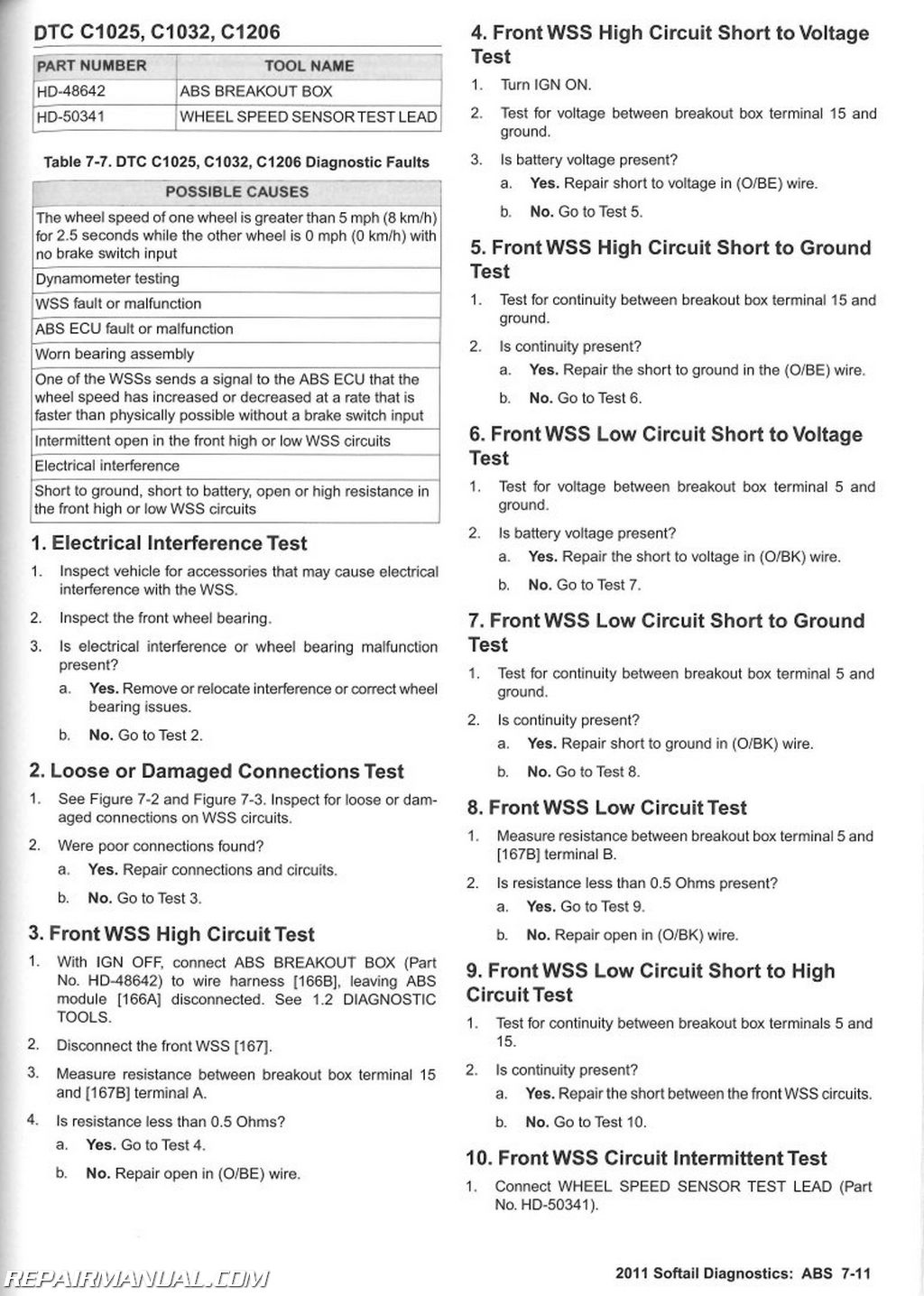
This Official 2011 Harley Davidson Softail Electrical Diagnostic Manual provides electrical diagnostic information and wiring diagrams for 2011 Harley Davidson Softail motorcycles including:
2011 Harley-Davidson FXSTC Softail Custom (Softail)
2011 Harley-Davidson FXSTB Night Train (Softail)
2011 Harley-Davidson FXST Softail Standard (Softail)
2011 Harley-Davidson FXCWC Softail Rocker Custom (Softail)
2011 Harley-Davidson FXCW Softail Rocker (Softail)
2011 Harley-Davidson FLSTSB Softail Cross Bones (Softail)
2011 Harley-Davidson FLSTN Softail Deluxe (Softail)
2011 Harley-Davidson FLSTF Shrine (Softail)
2011 Harley-Davidson FLSTF Fat Boy (Softail)
2011 Harley-Davidson FLSTC Shrine (Softail)
2011 Harley-Davidson FLSTC Heritage Softail Classic (Softail)
2011 Harley Davidson Softail Electrical Diagnostic Manual Table of Contents
Chapter 1 General Information
Chapter 2 Initial Diagnostics and Serial Data
Chapter 3 Starting and Charging
Chapter 4 Instruments
Chapter 5 Accessories, Horn, Lighting and Security
Chapter 6 Engine Management
Chapter 7 ABS
Appendix A Connector Repair
Appendix B Wiring
Appendix C Conversions
Appendix D Glossary
2011 Harley Davidson Softail Electrical Diagnostic Manual Index of Topics
CHAPTER 1: GENERAL INFORMATION
1.1 SPECIFICATIONS AND COMPONENT LOCATIONS
Specifications.
Component Locations
1.2 DIAGNOSTIC TOOLS
How To Use Diagnostic Tools
HD-26792 Spark Tester
HD-34730-2D Fuel Injector Test Light
HD-39978 Digital Multimeter (Fluke 78)
HD-39617 Fluke AC/DC Current Probe.
HD-41199-3 I AC Test Light
HD-41404-C Harness Connector Test Kit.
HD-50341 Wheel Speed Sensor Test Lead.
HD-42682 Breakout Box (Instruments)
HD-43876 Breakout Box (ECM)
HD-50390-1 Breakout Box (BCM)
HD-44687 Ignition Coil Circuit Test Adapter.
HD-48642 Breakout Box (ABS)
HD-48053 Advanced Battery Conductance and Electrical
System Analyzer
HD-48650 Digital Technician II
1.3 DIAGNOSTICS AND TROUBLESHOOTING
Voltage Drop
Voltage Drop Test
Wiggle Test.
Job/Time Codes Values
CHAPTER 2: INITIAL DIAGNOSTICS AND SERIAL DATA
2.1 INITIAL DIAGNOSTICS
Description and Operation.
Retrieving Trouble Codes
Odometer Self-Diagnostics.
Diagnostic Mode
Initial Diagnostics.
1. DTC Test.
2. Odometer Function Test
3. Odometer Inoperative Test
4. Battery Power Test
5. Starter Test
6. LHCM Test
Diagnostics
Diagnostic Tips
Code Types.
Current
Historic.
Multiple Trouble Codes.
Clearing DTCs.
Security Lamp.
Check Engine Lamp
Symptoms
2.2 SERIAL DATA COMMUNICATION
Description and Operation.
Components.
Electronic Control Module (ECM)
Speedometer.
BCM
ABS Module.
Hand Control Modules
Data Link Connector (DLC).
Communication DTCs and Error Messages
Diagnostic Tips
2.3 ODOMETER SELF-DIAGNOSTIC INOPERATIVE, DTC U0001, U0Q11, B2274
Description and Operation
Diagnostic Tips
Connector Information
Odometer Self-Diagnostic Inoperative, DTC U0001, U0011, B2274
1. CAN Bus Shorted Together Test
2. Speedometer Test.
3. ECM Test
4. LHCM Test
5. RHCM Test
6. BCM Test
7. ABS Test
8. CAN High Circuit Short to Voltage Test
9. Speedometer Test.
10. ECM Test
11. LHCM Test.
12. RHCM Test.
13. BCM Test
14. ABS Test
15. CAN High Circuit Short to Ground Test
16. Speedometer Test
17. ECM Test
18. LHCM Test.
19. RHCM Test.
20. BCM Test
21. ABS Test
22. CAN Low Circuit Short to Voltage Test
23. Speedometer Test
24. ECM Test
25. LHCM Test.
26. RHCM Test.
27. BCM Test
28. ABS Test
29. CAN Low Circuit Short to Ground Test.
30. Speedometer Test
31. ECM Test
32. LHCM Test.
33. RHCM Test.
34. BCM Test
35. ABS Test
36. CAN High Circuit Continuity Test
37. CAN Low Circuit Continuity Test
38. Speedometer Power Test
39. Speedometer Ground Test
40. ECM Power Test
2.4 NO VEHICLE POWER OR DTC U0100, U0121, U0140, U0141, U0142, U0156
Description and Operation
Diagnostic Tips
Connector Information
DTC U0100.
1. ECM Voltage Test.
2. System Power Test
3. ECM Ground Test
4. CAN High Circuit Continuity Test
5. CAN Low Circuit Continuity Test.
DTC U0121.
1. ABS Voltage Test.
2. ABS Ground Test
3. CAN High Circuit Continuity Test
4. CAN Low Circuit Continuity Test.
No Vehicle Power, DTC U0140.
1. Ignition Switch Ground Test
2. Ignition Switch Test
3. Ignition Switch Accessory Test
4. Ignition Switch Signal Test
5. Switch Signal Short to Ground Test.
6. Ignition Switch Signal Short to Voltage Test
7. BCM Ground Test
8. CAN High Circuit Continuity Test
9. CAN Low Circuit Continuity Test.
10. BCM Voltage Test
Left Hand Controls Inoperative, DTC U0141
1. LHCM Voltage Test
2. LHCM Test
3. CAN High Circuit Continuity Test
4. CAN Low Circuit Continuity Test.
DTC U0142.
1. RHCM Voltage Test
2. RHCM Ground Test.
3. CAN High Circuit Continuity Test
4. CAN Low Circuit Continuity Test.
DTC U0156.
1. Speedometer Voltage Test
2. Speedometer Ground Test
3. CAN High Circuit Continuity Test
4. CAN Low Circuit Continuity Test.
CHAPTER 3: STARTING AND CHARGING
3.1 BATTERY TESTING
General
Voltmeter Test
Conductance Test
Load Test.
3.2 STARTING SYSTEM
Description and Operation
Components
Starter.
Starter Solenoid.
Engine Stop Switch
Start Switch
BCM
Ignition Switch
Battery.
Grinding Noise or Erratic Starting.
Job/Time Code Values
Connector Information
Starter Troubleshooting
Starter Testing.
1. Starting System Operational Test
2. Audible Noise Test
3. Starter Solenoid Test
4. Checking DTCs Test
Nothing Clicks
1. Battery Test
2. Fuse Test
3. Ignition Circuit Test
4. Starter Solenoid Circuit Test
5. Starter Ground Test
6. Neutral Switch Test
7. Starter Solenoid Circuit Test
8. BCM Test
Starter Solenoid Clicks.
1. Battery Test.
2. Starter Voltage Drop Test
3. Starter Solenoid Voltage Drop Starter Side Test
4. Starter Solenoid Battery Side Voltage Drop Test
5. Starter Ground Circuit Voltage Drop Test
6. Starter Ground Test
7. Starter Draw Test
8. Mechanical Binding Test
Starter Spins But Does Not Engage
1. Pinion Gear and Clutch Shell Test
Starter Stalls or Spins Too Slowly
1. Battery Test.
2. Starter Stud Voltage Drop Test.
3. Starter Ground Circuit Voltage Drop Test
4. Starter Draw Test
5. Starter Solenoid Voltage Drop Starter Side Test
6. Starter Solenoid Battery Side Voltage Drop Test
3.3 DTC B2121, B2122, B2123, B2124
Description and Operation
Conditions for Setting
Connector Information.
DTC B2121
1. Starter Solenoid Circuit Test
2. Starter Solenoid Supply Voltage Test.
DTC B2122
1. Starter Solenoid Circuit Test
2. Starter Solenoid Supply Voltage Test.
DTC B2123
1. Starter Solenoid Supply Continuity Test
DTC B2124
1. Starter Solenoid [128] Test.
2. Starter Solenoid Circuit Test
3. Starter-Solenoid Supply Continuity Test.
3.4 TESTING STARTER ON MOTORCYCLE
Starter Current Draw Test
3.5 TESTING STARTER ON BENCH
Free Running Current Draw Test
Starter Solenoid
Solenoid Pull-In Test
Solenoid Hold-lnTest.
Solenoid Return Test.
3.6 CHARGING SYSTEM
Description and Operation
Alternator
Voltage Regulator
Troubleshooting
Battery
Wiring.
Voltage Regulator Inspection
Job/Time Code Values
Connector Information.
Low or No Charging
1. Battery Test.
2. Off Idle Voltage Test.
3. AC Output Test
4. Stator Test
5. Rotor Inspection Test.
6. Voltage Regulator Power Circuit Test.
7. Voltage Regulator Ground Circuit Test
Overcharging
1. Battery Voltage Test
2. Voltage Regulator Ground Circuit Test
Low Battery After Extended IGN OFF
1. Battery Test.
2. Amp Draw Test
Battery Runs Down During Use
1. Total Current Draw Test
2. Battery Test.
Battery Charging Tests
Milliampere Draw Test.
Total Current Draw and Output Test
Stator Test
AC Output Test
3.7 DTC C0562, C0563, C1222, C1223
Description and Operation
DTC C0562 and C0563
DTC C1222 and C1223
Diagnostics.
Diagnostic Tips.
Connector Information.
DTC C0562
1. Battery Test.
2. Charging System Test
3. ABS ECU Battery Voltage Test
4. ABS ECU Battery Voltage Drop Test.
5. ABS ECU Ground Circuit Voltage Test
6. Main Fuse Voltage Drop Test.
7. Fuse Block Voltage Drop Test
8. Fuse Block Supply Voltage Drop Test
9. Repair Validation Test
DTC C0563
1. Charging System Test
2. Repair Validation Test
DTC C1222, C1223
1. ABS ECU Battery Voltage Test
2. ABS ECU Battery Voltage Drop Test.
3. Repair Validation Test
3.8 DTC P0562
Description and Operation
Diagnostics.
Diagnostic Tips.
Connector Information.
DTC P0562
1. Battery Test.
2. Charging System Test
3. ECM Switched Voltage Test
4. ECM System Power Voltage Drop Test
5. ECM Ground Circuit Voltage Drop Test.
6. BCM System Power Test.
7. BCM Power Test
8. Main Fuse Voltage Test
9. Fuse Block Voltage Test
10. Fuse Block Supply Voltage Test
11. Repair Validation Test.
3.9 DTC B2203
Description and Operation.
Connector Information
DTC B2203
1. Ignition Continuity [242B] Test
2. Ignition Switch Run Test
3. Ignition Switch ACC Test
4. Ignition Switch OFF Test
3.10 DTC B2206, B2208
Description and Operation.
DTC B2206
1. BCM Supply Voltage Test.
2. BCM Voltage Test
DTC B2208
1. BCM to Ground Continuity Test.
2. BCM Voltage Test
3.11 DTC B2271, B2272
Description and Operation.
DTC B2271
DTC B2272
Diagnostic Tips
Connector Information
DTC B2271
1. Battery Test
2. Charging System Test.
3. BCM Power Test.
4. Main Fuse Voltage Test
5. Fuse Block Voltage Test.
6. Fuse Block Supply Voltage Test
7. Repair Validation Test
DTC B2272
1. Charging System Test.
2. Repair Validation Test
CHAPTER 4: INSTRUMENTS
4.1 INSTRUMENTS
Description and Operation
Trip Odometer Reset Switch Operation.
Speedometer Theory of Operation
Instrument Diagnostics
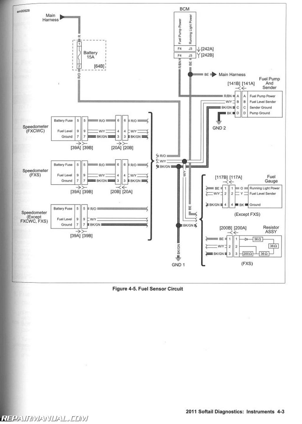
4.2 FUEL GAUGE INACCURATE, DTC B1210, B1211
Description and Operation
Connector Information.
DTC B1210: Except FXS
1. Fuel Level Sender Voltage Test.
2. Fuel Pump and Sender Test
3. Fuel Gauge Voltage Test
4. Fuel Gauge Circuit Test .
5. Fuel Gauge Circuit Test
DTC B1210: FXS.
1. Fuel Level Sender Voltage Test.
2. Fuel Pump and Sender Test
3. Fuel Gauge Voltage Test
4. Fuel Level Sender Circuit Test
5. Fuel Level Sender Circuit Test
DTC B1211: Except FXS.
1. Fuel Level Sender Voltage Test
2. Fuel Pump and Sender Test
3. Fuel Level Sender Circuit Short to Voltage Test.
4. Fuel Level Sender Circuit Open Test.
5. Fuel Level Sender Ground Circuit Test
6. Fuel Gauge Ground Circuit Test
7. Fuel Sender Resistance Test
8. Fuel Gauge Voltage Test.
9. Fuel Gauge Test
DTC B1211: FXS
1. Fuel Level Sender Voltage Test
2. Fuel Pump and Sender Test
3. Fuel Level Sender Circuit Short to Voltage Test
4. Fuel Level Sender Circuit Open Test.
5. Fuel Level Sender Ground Circuit Test
6. Resistor Assembly Ground Circuit Test
7. Fuel Sender Resistance Test
8. Resistor Assembly Voltage Test
9. Resistor Assembly Test
4.3 TRIP ODOMETER FUNCTIONS INOPERATIVE, DTC B2255
Description and Operation
Trip Odometer Reset Switch Closed
Connector Information
Trip Odometer Functions Inoperative, DTC B2255
1. Odometer Test
2. Speedometer “WOW” Test
3. LHCM Test
4. LHCM Power Test
5. LHCM Ground Test
6. CAN Low Circuit Open Test
7. CAN High Circuit Open Test.
4.4 NO INSTRUMENT POWER, DTC B1200
Description and Operation
Connector Information
No Instrument Power
1. Battery Circuit Test.
2. Accessory Function Test.
3. Battery Fuse Test.
4. Battery Circuit to Speedometer Test.
5. Battery Circuit Short to Ground Test
6. Ground Circuit Test
DTC B1200.
1. Speedometer Voltage Test
2. Speedometer Ground Test.
4.5 INDICATOR LAMPS
Description and Operation
ABS Indicator
Security Lamp
Check Engine Lamp.
Low Battery Lamp
Low Fuel Indicator
Neutral Indicator.
Oil Pressure Indicator
Turn Signal Indicators
High Beam Indicator
Sixth Gear Indicator
Connector Information
Oil Pressure Lamp Always On.
1. Oil Pressure Lamp Function Test.
2. Engine Running Test.
3. Oil Pressure Sensor Test
4. Oil Pressure Circuit Test.
5. Mechanical Test
6. Oil Pressure Switch Circuit Test
7. Speedometer Test.
Oil Pressure Lamp Inoperative
1. Oil Pressure Lamp Function Test.
2. Speedometer Test.
3. Oil Pressure Circuit Test.
Neutral Lamp Always On
1. Neutral Lamp Function Test
2. DTC Test
3. Indicator Harness Test.
Neutral Lamp Inoperative.
1. Neutral Lamp Function Test
2. BCM Message Test.
3. Neutral Switch Test.
4. Ground Wire Test.
5. Neutral Switch Power Circuit Open Test
6. Speedometer Test.
7. Neutral Indicator Circuit Test
High Beam Indicator Lamp Always On
1. High Beam Indicator Function Test
2. High Beam Indicator Circuit Test
3. High Beam Indicator Circuit Short to Ground Test.
High Beam Indicator Lamp Inoperative.
1. High Beam Indicator Function Test
2. High Beam Indicator Circuit Test
3. High Beam Indicator Circuit Open Test.
Turn Signal Indicator Lamp Always On.
1. Turn Signal Function Test.
2. Turn Signal Indicator Circuit Test.
3. Turn Signal Indicator Circuit Short to Ground Test.
Turn Signal Indicator Inoperative.
1. Turn Signal Function Test.
2. Turn Signal Indicator Circuit Test.
3. Turn Signal Indicator Circuit Open Test
4.6 GAUGES
Theory of Operation
Fuel Gauge Inaccurate, No DTCs.
1. Fuel Gauge Test
2. Sending Unit Test
3. Fuel Gauge Circuit Test
Fuel Gauge Inoperative
1. Ignition Voltage Test
2. Ground Circuit Test.
CHAPTER 5: ACCESSORIES, HORN, LIGHTING AND SECURITY
5.1 ACCESSORIES, DTC B2112, B2113, B2114
Description and Operation
Conditions for Setting
Diagnostic Tips
Connector Information
DTC B2112
1. Accessory Power Circuit Short to Voltage Test
2. BCM Test.
DTC B2113, B2114.
1. Accessory Power Circuit Short to Ground Test.
2. Accessory Circuit Test
3. BCM Test.
5.2 HORN, DTC B2126, B2127, B2128, B2129
Description and Operation.
Conditions for Setting
Diagnostic Tips
Connector Information
DTC B2126
1. Horn Test
2. Ground Circuit Open Test
3. Power Circuit Open Test.
DTC B2127
1. Horn Power Circuit Short to Voltage Test
2. DTC Test.
DTC B2128, B2129.
1. Horn Circuit Test.
2. DTC Test.
5.3 TURN SIGNALS
Description and Operation.
Manual Cancellation
Automatic Cancellation
Four-Way Flashing.
Tip Over Detection Operation
Tip Over Reset.
Connector Information
Will Not Cancel Upon Turn Completion, No DTCs
1. BCM Mounting Test.
2. Correct Configuration Test.
3. Turn Signals Cancel Test
4. Speedometer Test
5.4 DTC B1101, B1151
Description and Operation.
Conditions for Setting
Connector Information
DTC B1101, B1151.
1. Bulb Test
2. Socket and Wiring Inspection Test
5.5 DTC B2141, B2143, B2144, B2146, B2148, B2149
Description and Operation.
Conditions for Setting
Connector Information
DTC B2141
1. Bulb Test
2. Ground Circuit Open Test
3. Power Circuit Short to Voltage Test.
4. Power Circuit Open Test.
DTC B2143, B2144.
1.Bulb Test
2. Power Circuit Short to Ground Test.
3. DTC Test
DTC B2146.
1. Bulb Test
2. Ground Circuit Open Test
3. Power Circuit Short to Voltage Test
4. Power Circuit Open Test
DTC B2148, B2149
1. Bulb Test
2. Power Circuit Short to Ground Test.
3. DTC Test
5.6 DTC B2151, B2153, B2154, B2156, B2158, B2159
Description and Operation
Conditions for Setting.
Connector Information
DTC B2151: Except FXCWC
1. Left Rear Turn Signal Operation Test
2. Left Rear Turn Signal Bulb Test.
3. Ground Circuit Open Test
4. Power Circuit Short to Voltage Test
5. Power Circuit Open Test
DTC B2151: FXCWC
1. Left Rear Turn Signal Operation Test
2. Left Rear Turn Signal Test
3. Power Circuit Open Test
4. Ground Circuit Open Test
5. Power Circuit Short to Voltage Test
DTC B2153, B2154: Except FXCWC.
1. Bulb Test
2. Power Circuit Short to Ground Test.
DTC B2153, B2154: FXCWC
1. Left Rear Turn Signal Assembly Test
2. Power Circuit Short to Ground Test.
DTC B2156: Except FXCWC
1. Right Rear Turn Signal Operation Test.
2. Right Rear Turn Signal Test
3. Ground Circuit Open Test
4. Power Circuit Short to Voltage Test
5. Power Circuit Open Test
DTC B2156: FXCWC
1. Right Rear Turn Signal Operation Test.
2. Right Rear Turn Signal Test
3. Power Circuit Open Test
4. Ground Circuit Open Test
5. Power Circuit Short to Voltage Test
DTC B2158, B2159: Except FXCWC.
1. Bulb Test
2. Ground Circuit Open Test
DTC B2158, B2159: FXCWC
1. Right Rear Turn Signal Assembly Test
2. Power Circuit Short to Ground Test.
5.7 HEADLAMPS, DTC B2131, B2132, B2133, B2134, B2136, B2137, B2138, B2139
Description and Operation
Conditions for Setting.
Diagnostic Tips
Connector Information
Auxiliary Lamps Inoperative.
1. Auxiliary Lamps Operation Test
2. Auxiliary Bulb Test
3. Auxiliary Lamp Circuit Test
4. Auxiliary Lamp Switch Test.
5. Auxiliary Lamp Power Circuit Test
DTC B2131
1. Bulb Test
2. Headlamp Test
3. Ground Circuit Open Test
4. Power Circuit Open Test.
5. BCM Test.
DTC B2132
1. Headlamp Test
2. DTC Test.
DTC B2133, B2134.
1. High Beam Headlamp Circuit Test
2. DTC Test.
DTC B2136
1. Headlamp Test
2. Ground Circuit Open Test
3. Power Circuit Open Test.
4. BCM Test.
DTC B2137
1. Headlamp Test
2. DTC Test.
DTC B2138, B2139.
1. Low Beam Headlamp Circuit Test
2. DTC Test.
5.8 STOP LAMPS, DTC B2161, B2163, B2164, B2223
Description and Operation.
Conditions for Setting
Connector Information
Stop Lamp Always On.
1.BCM Test
DTC B2161: Except FXCWC
1. Stop Lamp Test.
2. Ground Circuit Open Test
3. Power Circuit Open Test.
DTC B2161: FXCWC (HDI Only)
1. BCM Test.
2. Stop Lamp Test.
3. Ground Circuit Open Test
DTC B2163, B2164: Except FXCWC
1. Stop Lamp Bulb Test
2. Stop Lamp Power Circuit Short to Ground Test.
DTC B2163, B2164: FXCWC (HDI Only).
1.Stop Lamp Power Circuit Short to Ground Test.
DTC B2223
1. Stop Lamp Switch Test
2. Brake Switch Short to Ground Test
3. DTC Test.
5.9 DTC B1103, B1153, B2250, B2251, B2252, B2253, B2254, B2260, B2261, B2262, B2263, B2270
Description and Operation.
Conditions for Setting
Diagnostic Tips
DTC B1103, B1153.
1.Hand Control Module Power Test
2.Ground Circuit Open Test~ -r~
DTC B2250, B2251, B2252, B2253, B2254, B2260, B2261,
B2262, B2263
1. Switch Test
DTC B2270
1. BCM Voltage Test
2. BCM Ground Test.
Any Hand Control Switch Inoperative.
1. Switch Operation Test.
2. Clutch or Front Brake Switch Test.
5.10 RUNNING LAMPS, DTC B2107, B2108, B2109, B2166, B2168, B2169
Description and Operation
Conditions for Setting
Connector Information.
Front Running Lamps Inoperative
1. Domestic Running Lamp Configuration Test
2. Bulb Test.
3. Running Lamp Test
4. Ground Circuit Test
Rear Running Lamps Inoperative: Except FXS
1. Running Lamps Configuration Test
2. Bulb Test.
3. Ground Circuit Test
4. Running Lamps Power Test.
5. Rear Running Lamps Ground Circuit Test
Rear Running Lamps Inoperative: FXS.
1. Bulb Test.
2. Ground Circuit Test
License Plate Lamp Inoperative: Except FXS
1. Running Lamps Configuration Test
2. Bulb Test.
3. Ground Circuit Test
4. License Plate Lamps Power Test.
5. License Plate Lamp Ground Circuit Test
License Plate Lamp Inoperative: FXS.
1. Bulb Test.
2. Ground Circuit Test
DTC B2107
1. Position Lamp Circuit Test
2. DTC Test
DTC B2108, B2109
1. Position Lamp Circuit Short to Ground Test.
2. Excessive Draw Test
3. DTC Test
DTC B2166 (Domestic Only)
1. DTC Test
2. Running Lamp Operation Test.
3. Running Lamp Short to Voltage Test
4. Running Lamps Circuit Test
5. Bulb Test.
6. Running Lamp Open Circuit Test.
7. Running Lamps Circuit Test
DTC B2168, B2169
1. Rear Running Lamps Circuit Test
2. Ground Circuit Open Test.
3. Front Running Lamp Circuit Test
4. BCM Test
DTC B2168, B2169: FXS
1. Right Rear Turn Lamp Circuit Test.
2. Left Rear Turn Lamp Circuit Test
3. Tail Lamp Circuit Test
4. Ground Circuit Open Test.
5. BCM Test
5.11 SECURITY SYSTEM
Security Lamp
Security Immobilization.
Security System Features
Warnings.
Arming
Disarming
Automatic Disarming
Disarming with a PIN
Alarm.
Activation
Deactivation of Alarm.
5.12 KEY FOB
Description and Operation
Fob Assignment.
5.13 SIREN
Description and Operation
Siren Chirp Mode Confirmation.
Chirpless Mode
Chirp Mode
Switching Modes.
5.14 SERVICE AND EMERGENCY FUNCTIONS AND CONFIGURATIONS
General
Actuation
Selecting a PIN
Initial PIN Entry.
Changing the PIN
Transport Mode.
To Enter Transport Mode
To Exit Transport Mode
Service Mode
Four-Way Flashing.
To Arm the Security System with the Hazard Warning
Flashers ON „ „ ,
To Disarm the Security System and Turn the Hazard Warning Flashers OFF
5.15 DTC B2172, B2173
Description and Operation
Diagnostic Tips.
Connector Information.
DTC B2172
1. Siren Circuit Short to Voltage Test
2. DTC Test
3. Siren Test
DTC B2173
1. Battery Circuit Test
2. Power Supply Circuit Test
3. Siren Signal Circuit Open Test.
4. Siren Signal Short to Ground Test.
5. Security Siren Resistance Test.
6. Security Siren Validation Test.
7. DTC Test
5.16 FAILS TO DISARM, DTC B2176, B2177,
B2178
Description and Operation.
Conditions for Setting
Diagnostic Tips
Connector Information
DTC B2176
1. Security Antenna Resistance Test.
2. Antenna B Circuit Open Test
3. Antenna A Circuit Open Test
4. DTC Test.
DTC B2177
1. Security Antenna Visual Test
2. Security Antenna High Circuit Short to Voltage Test
3. Security Antenna Low Circuit Short to Voltage Test
4. DTC Test.
DTC B2178
1. Security Antenna Visual Test
2. Security Antenna High Short to Ground Test
3. Security Antenna Low Short to Ground Test.
4. DTC Test.
Fails to Disarm
1. DTC Test.
2. Non-Functional Fob Test.
3. Interference Test.
4. Antenna Connection Test.
5. Antenna Circuit Short to Ground Test
6. Antenna Circuits Shorted Together Test.
7. Antenna Circuit Open Test
8. Security System Antenna Test
5.17 DTC B2218
Description and Operation.
Conditions for Setting
Connector Information
DTC B2218
1. Neutral Circuit Short to Ground Test
2. Neutral Switch Test
3. Neutral Switch Short to Ground Test.
4. DTC Test
CHAPTER 6: ENGINE MANAGEMENT
6.1 EFI SYSTEM
General
EFI Operation
Symptom Diagnostics
6.2 ELECTRONIC CONTROL MODULE
General
ECM
32-2 Crankshaft
Crank Position Signal Synchronization
Engine Phase
Engine Run Mode
6.3 SENSORS AND DRIVERS
Description and Operation
Sensors.
Crank Position (CKP) Sensor
Throttle Position Sensor (TPS)
Jiffy Stand Sensor (JSS)
Accelerometer
Clutch Switch
Neutral Switch.
Engine Temperature (ET) Sensor
Manifold Absolute Pressure (MAP) Sensor
Intake Air Temperature (IAT) Sensor.
Vehicle Speed Sensor (VSS).
02 Sensor: Front and Rear
Drivers.
Fuel Pump
Ignition Coils and Spark Plugs
Fuel Injectors.
Idle Air Control (IAC)
Active Intake Solenoid (AIS): HDI Only.
Active Exhaust Actuator: HDI Only
6.4 DTC B2102, B2103, B2104
Description and Operation.
Conditions for Setting
Diagnostic Tips
Connector Information
DTC B2102
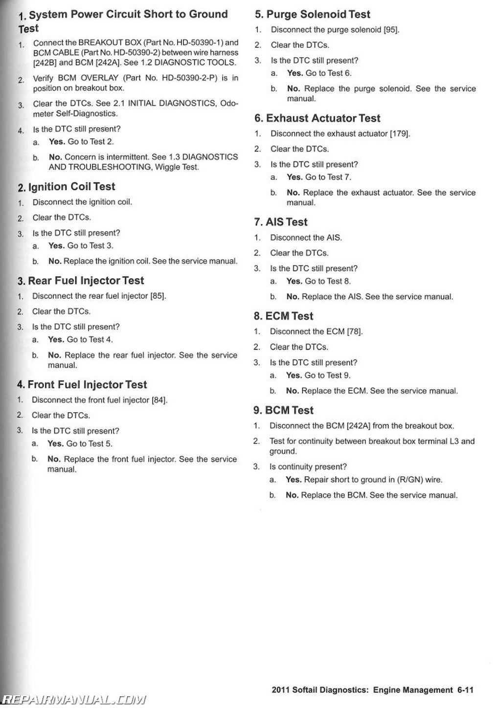
1. System Power Circuit Short to Voltage Test
DTC B2103, B2104.
1. System Power Circuit Short to Ground Test.
2. Ignition Coil Test
3. Rear Fuel Injector Test.
4. Front Fuel Injector Test
5. Purge Solenoid Test
6. Exhaust Actuator Test
7. AIS Test.
8. ECM Test.
9. BCM Test.
6.5 DTC B2116, B2117, B2118, B2119
Description and Operation.
Conditions for Setting
Diagnostic Tips
Connector Information
DTC B2116
1. Fuel Pump Circuit Test
2. Fuel Pump Ground Circuit Open Test
3. Fuel Pump Power Circuit Open Test
DTC B2117
1. Fuel Pump Power Circuit Short to Voltage Test
2. Code Verification Test
DTC B2118, B2119.
1. Fuel Test
2. Fuel Pump Test.
3. Fuel Pump Power Circuit Short to Ground Test
6.6 DTC P0107, P0108
Description and Operation.
Diagnostic Tips
Connector Information
DTC P0107
1. MAP Sensor Test
2. MAP Sensor Signal Voltage Test
3. MAP Sensor Signal Wire Continuity Test
4. MAP Sensor Signal Wire Shorted to Ground Test
5. MAP Sensor Signal Wire Shorted to Sensor Ground Test
6. MAP Sensor 5V Reference Wire Open Test
7. MAP Sensor 5V Reference Shorted to Signal Ground Test
DTC P0108
1. MAP Sensor Test.
2. MAP Sensor Signal Wire Short to 5V Test.
3. MAP Sensor Signal Wire Short to Voltage Test
4. MAP Sensor 5V Reference Shorted to Battery Voltage Test
5. MAP Sensor Ground Wire Open Test
6.7 DTC P0112, P0113
Description and Operation
Diagnostic Tips.
Connector Information.
DTC P0112
1. IAT Sensor Test.
2. IAT Sensor Signal Wire Shorted to Ground Test
3. IAT Sensor Signal Voltage High Test
4. IAT Sensor Signal Wire Shorted to Sensor Ground Test
DTC P0113
1. IAT Sensor Test.
2. IAT Sensor Signal Wire Open Test
3. IAT Sensor Open Ground Wire Test
4. IAT Sensor Signal Wire Shorted to Sensor Power Test
6.8 DTC P0117, P0118
Description and Operation
Diagnostic Tips.
Connector Information.
DTC P0117
1. ET Sensor Test
2. ET Sensor Signal Wire Shorted to Ground Test.
3. ET Sensor Signal Wire Shorted to Sensor Ground Test
DTC P0118
1. ET Sensor Test
2. ET Sensor Signal Wire Open Test
3. ET Sensor Open Ground Wire Test
4. ET Sensor Signal Wire Shorted to Sensor Power Test
6.9 DTC P0122, P0123
Description and Operation
Diagnostic Tips.
Connector Information.
DTC P0122
1. TPS Test
2. TPS Signal Voltage Test
3. TPS Signal Wire Continuity Test
4. TPS Signal Wire Shorted to Ground Test
5. TPS Signal Wire Shorted to Sensor Ground Test.
6. TPS 5V Sensor Power Open Wire Test
DTC P0123
1. TPS Test.
2. TPS Signal Wire Short to 5V Test. c 00
3. TPS Signal Wire Short to Voltage Test
4. TPS 5V Shorted to Battery Voltage Test.
5. TPS Ground Wire Open Test
6.10 DTC P0131, P0132, P0134, PQ151, P0152, P0154
Description and Operation
Diagnostic Tips
Connector Information
DTC P0131.
1. Front 02 Sensor Test.
2. Front 02 Sensor Signal Wire Shorted to Sensor Ground Test
3. Front 02 Sensor Signal Wire Shorted to Ground Test
4. Front 02 Sensor Operation Test
DTC P0132.
1. Front 02 Sensor Operation Test
DTC P0134.
1. Front 02 Sensor Signal Wire Short Circuit Voltage Test
2. Front 02 Sensor Open Sensor Ground Test
3. Front 02 Sensor Signal Wire Open Test
DTC P0151.
1. Rear 02 Sensor Test
2. Rear 02 Sensor Signal Wire Shorted to Sensor Ground Test
3. Rear 02 Sensor Signal Wire Shorted to Ground Test
4. Rear 02 Sensor Operation Test.
DTC PO152.
1. Rear 02 Sensor Operation Test
DTC P0154.
1. Rear 02 Sensor Signal Wire Short Circuit Voltage Test
2. Rear 02 Sensor Open Sensor Ground Test.
3. Rear 02 Sensor Signal Wire Open Test
6.11 DTC P0261, P0262, P0264, P0265
Description and Operation
Connector Information
DTC P0261.
1. Front Fuel Injector Test
2. Front Fuel Injector Power Wire Open Circuit Test
3. Front Fuel Injector Power Wire Shorted to Ground Test
4. Injector Resistance Test
5. Driver Short to Ground Test
DTC P0262.
1. Front Fuel Injector Control Wire Shorted to Voltage Test
2. Injector Resistance Test
DTC P0264.
1. Rear Fuel Injector Test.
2. Rear Fuel Injector Power Wire Open Circuit Test
3. Rear Fuel Injector Power Wire Shorted to Ground Test
4. Injector Resistance Test
5. Driver Short to Ground Test
DTC P0265.
1. Rear Fuel Injector Control Wire Shorted to Voltage Test.
2. Injector Resistance Test
6.12 DTC P0371, P0372, P0374
Description and Operation
Diagnostic Tips
Connector Information
DTC P0371, P0372, P0374
1. CKP Sensor Connections Test
2. CKP Sensor Signal Wire Continuity Test
3. CKP Sensor Ground Wire Continuity Test
4. CKP Sensor Signal Wire Shorted to CKP Ground Wire Test.
5. CKP Sensor Low Shorted to Ground Test.
6. CKP Sensor Output Test.
7. CKP Sensor Signal Wire Shorted to Ground Test.
8. CKP Sensor Voltage Test
6.13 DTC P0444, P0445
Description and Operation
Purge Solenoid (CA and Select Foreign Market Models Only)
Connector Information
DTC P0444.
1. Purge Solenoid Test.
2. Purge Solenoid Voltage Test
3. Purge Solenoid Control Wire Shorted to Ground Test.
4. Purge Solenoid Control Wire Open Test.
5. Purge Solenoid Power Wire Open Test
DTC P0445.
1. Purge Solenoid Test.
2. Purge Solenoid Short to Voltage Test
6.14 DTC P0502, P0503
Description and Operation
Connector Information
DTC P0502.
1. VSS Connections Test
2. VSS Sensor Power Short to Ground Test.
3. VSS Signal Wire Short to Ground Test
4. VSS Signal Wire Open Test.
5. VSS Dirty or Damaged Test.
DTC P0503.
1. VSS Sensor Power Shorted to Voltage Test.
2. VSS Signal Wire Short to Voltage Test.
3. VSS Ground Wire Open Test.
4. VSS Signal Wire Shorted to Sensor Power Test
5. VSS Test
6.15 DTC P0506, P0507
Description and Operation
Diagnostic Tips
Connector Information
DTC P0506, P0507
1. IAC Operational Test
2. IAC Connector Test
3. IAC Circuits Open Test.
4. IAC Circuits Shorted to Ground Test
5. IAC Circuits Short to Voltage Test.
6. Short Between IAC Circuits Test.
7. System Power Circuit Open Test.
6.16 DTC P0603, P0605
Description and Operation
DTC P0603 Test
DTC P0605 Test
6.17 DTC P0641
Description and Operation
Connector Information
DTC P0641.
1. 5V Sensor Short to Voltage Test.
2. TPS 5V Sensor Power Circuit Below Range Test.
3. MAP Sensor 5V Sensor Power Circuit Below Range Test.I
4.VSS 5V Sensor Power Circuit Below Range Test(
5. JSS 5V Sensor Power Circuit Below Range Testi
6. 5V Sensor Power Circuit Short to Ground Test I
7. 5V Sensor Power Circuit Shorted to Sensor Ground Circuit Test
6.18 DTC P0661, P0662
Description and Operation
Connector Information
DTC P0661, P0662
1. AIS Test
2. AIS Resistance Test.
3. AIS Open Ground Wire Test.
4. AIS Low Short to Ground Test.
5. AIS Open Supply Wire Test.
6.19 DTC P1009
General
Password Problem.
DTC P1009.
1. Incorrect Password Test
2. BCM Replacement Test
6.20 DTC P1353, P1356, P1357, P1358
Description and Operation
Connector Information
DTC P1353, P1356
1. Absence of Fuel Test
2. Ion Sense Continuity Test.
3. Ion Sense Short to Voltage Test.
4. Spark Plug Cable Test
5. Ignition Rear Coil Primary Resistance Test
6. Ignition Front Coil Primary Resistance Test.
7. Ignition Coil Secondary Resistance Test
8. Ion Sense Coil Resistance Test
DTC P1357, P1358
1. Spark Plug Cable Test
2. Ion Sense Continuity Test.
3. Ion Sense Short to Voltage Test.
4. Ion Sense Resistance Test.
6.21 DTC P1475, P1477, P1478
Description and Operation
Connector Information
DTC P1475.
1. Exhaust Actuator Test.
2. Exhaust Actuator Voltage Test.
3. Exhaust Actuator Motor Ground Wire Continuity Test
4. Exhaust Actuator Motor Power Wire Continuity Test
5. Exhaust Actuator Feedback Voltage Test.
6. Exhaust Actuator Feedback Continuity Test.
7. Exhaust Actuator Feedback Control Test.
8. Exhaust Actuator Feedback Run Test
9. Exhaust Actuator Feedback Short to Voltage Test
10. Exhaust Actuator Feedback Short to Ground Test
DTC P1477
1. Exhaust Actuator Motor Open Test.
2. Exhaust Actuator Motor Shorted to Ground Test.
3. Exhaust Actuator Feedback Shorted to Ground Test
DTC P1478
1. Exhaust Actuator Motor High Test.
2. Exhaust Actuator Motor Shorted to Voltage Test.
6.22 DTC P1501, P1502
Description and Operation.
Connector Information
DTC P1501
1. JSS 5V Reference Open Circuit Test
2. JSS 5V Reference Shorted to Ground Test
3. JSS Signal Wire Shorted to Ground Test.
4. JSS Signal Wire Open Circuit Test
DTC P1502
1. JSS Ground Wire Test.
2. JSS 5V Reference Wire Short to Voltage Test.
3. JSS Signal Wire Short to Voltage Test
4. JSS 5V Reference and Signal Shorted Together Test
Side Stand Displayed on Speedometer
1. Starts, Then Stalls Test
2. Neutral Test
3. JSS Clearance Test
6.23 DTC P1632
Description and Operation.
6.24 DTC P2300, P2301, P2303, P2304
Description and Operation.
Connector Information
DTC P2300
1. Ignition Coil Test
2. Ignition Coil Input Voltage Test.
3. Ignition Coil Control Wire Continuity Test
4. Iqnition Coil Control Wire Shorted to Ground Test
DTC P2301
1. Ignition Coil Shorted to Voltage Test
2. Ignition Coil Open Test.
DTC P2303
1. Ignition Coil Test
2. Ignition Coil Input Voltage Test.
3. Ignition Coil Control Wire Continuity Test
4. Iqnition Coil Control Wire Shorted to Ground Test
DTC P2304.
1. Ignition Coil Shorted to Voltage Test.
2. Ignition Coil Open Test
6.25 ENGINE CRANKS, BUT WILL NOT START
Description and Operation
Engine Cranks but Will Not Start
1. Preliminary Engine Tests
2. I AC Operation Test.
3. Spark Present Test
6.26 STARTS, THEN STALLS
Description and Operation
Diagnostic Tips
Connector Information
Starts, Then Stalls
1. Throttle Test.
2. Fuel System Test.
3. System Power Test
6.27 MISFIRE AT IDLE OR UNDER LOAD
Description and Operation
Diagnostic Tips
In-line Spark Tester
Connector Information
Misfire At Idle or Under Load
1. Power Ground Continuity Test.
2. Spark Test.
3. Spark Plug Wire Test
4. Carbon Tracking Inspection Test.
5. Ignition Coil Primary Wire Continuity Test
6. Battery to Main Fuse Block Voltage Drop Test.
CHAPTER 7:ABS
7.1 ANTI-LOCK BRAKE SYSTEM (ABS) GENERAL INFORMATION
Description and Operation
ABS CAN Communication Functionality
Pressure Hold
Pressure Decrease
Pressure Increase
Initialization Self-Test.
ABS Indicator
7.2 DTC C1018, C1041, C1042, C1044, C1224, C1225
Description and Operation
Conditions for Setting the DTC.
Action Taken When the DTC Sets.
Diagnostic Tips.
Connector Information.
DTC C1018, C1042, C1224.
1. Front HCU Internal Power Circuit Short to Ground Test
2. Front HCU Internal Power Circuit Short to Voltage Test
3. Front HCU Ground Circuit Test
4. Front HCU Power Circuit Test
5. Pump Motor Current Draw Test
6. ABS ECU Test
DTC C1041. C1044, C1225
1. Rear HCU Internal Power Circuit Short to Ground Test
2. Rear HCU Internal Power Circuit Short to Voltage Test
3. Rear HCU Ground Circuit Test
4. Rear HCU Power Circuit Test
5. Pump Motor Current Draw Test
6. ABS ECU Test
7.3 DTC C1021,01023
Description and Operation.
Conditions for Setting the DTC
Action Taken When the DTC Sets
Diagnostic Tips
Connector Information
DTC C1021 (Front), C1023 (Rear).
1. Electrical Interference Test
2. Validation of Current DTC Test
3. Worn or Damaged Components Test
7.4 DTC C1025, C1032, C1206
Description and Operation
Conditions for Setting the DTC.
Action Taken When the DTC Sets
Diagnostic Tips.
Connector Information.
DTC C1025, C1032, C1206.
1. Electrical Interference Test
2. Loose or Damaged Connections Test.
3. Front WSS High Circuit Test
4. Front WSS High Circuit Short to Voltage Test.
5. Front WSS High Circuit Short to Ground Test
6. Front WSS Low Circuit Short to Voltage Test
7. Front WSS Low Circuit Short to Ground Test
8. Front WSS Low Circuit Test.
9. Front WSS Low Circuit Short to High Circuit Test
10. Front WSS Circuit Intermittent Test
11. Front WSS Test
7.5 DTC C1027, C1034, C1208
Description and Operation.
Conditions for Setting the DTC
Action Taken When the DTC Sets
Diagnostic Tips
Connector Information
DTC C1027, C1034, C1208
1. Electrical Interference Test
2. Loose or Damaged Connections Test
3. Rear WSS High Circuit Test.
4. Rear WSS High Circuit Short to Voltage Test
5. Rear WSS High Circuit Short to Ground Test
6. Rear WSS Low Circuit Short to Voltage Test
7. Rear WSS Low Circuit Short to Ground Test.
8. Rear WSS Low Circuit Test
9. Rear WSS Low Circuit Short to High Circuit Test
10. Rear WSS Circuit Intermittent Test.
11. Rear WSS Test.
7.6 DTC C1052, C1102
Description and Operation.
Conditions for Setting the DTC
Action Taken When the DTC Sets
Diagnostic Tips
Connector Information
DTC C1052, C1102.
1. Rear HCU Internal Power Circuit Short to Ground Test
2. Pump Motor Current Draw Test
3. ABS ECU Test
7.7 DTC C1055
Description and Operation.
Circuit Description
Conditions for Setting the DTC
Action Taken When the DTC Sets
Diagnostic Tips
Connector Information
DTC C1055
1. Battery Circuit Voltage Test
2. Battery Power Circuit Resistance Test
3. Ground Circuit Resistance Test
7.8 DTC C1094
Description and Operation.
Conditions for Setting the DTC
Action Taken When the DTC Sets
Diagnostic Tips
Connector Information
DTC C1094
1. Validation of Current DTC Test
2. Brake Lamp Operation Test
3. BCM DTC Test
7.9 DTC C1151, C1153
Description and Operation.
Conditions for Setting the DTC
Action Taken When the DTC Sets
Diagnostic Tips
DTC C1151
1. Validation of Current DTC Test
2. Brake System Test.
3. ABS ECU Test
DTC C1153
1. Validation of Current DTC Test
2. Brake System Test.
3. ABS ECU Test
7.10 DTC C1158, C1178, C1184
Description and Operation.
Conditions for Setting the DTC
Action Taken When the DTC Sets
Diagnostic Tips
DTC C1158
1. Validation of Current DTC Test
2. Successful Calibration Test
DTC C1178, C1184.
1. Validation of Current DTC Test
2. Successful Calibration Test
3. Speedometer Test
7.11 DTC C1192, C1193
Description and Operation.
Conditions for Setting the DTC
Action Taken When the DTC Sets
Diagnostic Tips
Connector Information
DTC C1192, C1193.
1. Front HCU Internal Power Circuit Short to Ground Test
2. Pump Motor Current Draw Test
3. ABS ECU Test
7.12 DTC C1212
Description and Operation.
Conditions for Setting the DTC
Action Taken When the DTC Sets
Diagnostic Tips
Connector Information
DTC C1212
1. Validation of Current DTC Test
2. Brake Lamp Operation Test
3. BCM DTC Test
7.13 DTC C1561, C1562, C1563, C1564, C1565
Description and Operation.
Conditions for Setting the DTC
Action Taken When the DTC Sets
Diagnostic Tips
Connector Information
DTC C1561-C1565
1. Front HCU Apply Solenoid Circuit Short to Ground Test
2. Front Release Solenoid Circuit Short to Ground Test
3. Front HCU Apply Solenoid Circuit Short to Voltage Test
4. Front Release Solenoid Circuit Short to Voltage Test
5. Front HCU Apply Circuit Resistance Test
6. Front HCU Release Circuit Resistance Test.
7. Front HCU Apply and Release Circuits Test.
8. Front HCU Apply and Release Circuits Test.
9. Front HCU Diode Test A
10. Front HCU Diode Test B.
11. ABS ECU Test
7.14 DTC C1567, C1568, C1571, C1572, C1573
Description and Operation.
Conditions for Setting the DTC
Action Taken When the DTC Sets
Diagnostic Tips
Connector Information
DTC C1567, C1568, C1571, C1572, C1573.
1. Rear HCU Apply Solenoid Circuit Short to Ground Test
2. Rear Release Solenoid Circuit Short to Ground Test
3. Rear HCU Apply Solenoid Circuit Short to Voltage Test
4. Rear Release Solenoid Circuit Short to Voltage Test.
5. Rear HCU Apply Circuit Resistance Test
6. Rear HCU Release Circuit Resistance Test.
7. Rear HCU Apply and Release Circuits Test.
8. Rear HCU Test.
9. Rear HCU Diode Test A
10. Rear HCU Diode Test B.
11. ABS ECU Test.
7.15 ABS INDICATOR ALWAYS ON OR INOPERATIVE
Description and Operation
Diagnostic Tips
Connector Information
ABS Indicator Always On or Inoperative
1. DTC Test
2. ABS Lamp Function Test.
3. CAN High Circuit Continuity Test
4. CAN Low Circuit Continuity Test.
5. ABS Power Circuit Test.
6. ABS Ground Circuit Test
7. ABS ECU Test
APPENDIX A CONNECTOR REPAIR
A.1 AUTOFUSE UNSEALED ELECTRICAL CONNECTORS
Autofuse Unsealed Connector Repair
General
Disassembly
Assembly
A.2 DELPHI 100W MICRO-PACK SEALED CONNECTOR
Delphi 100W Micro-Pack Sealed Connector Repair
General
Separating Socket Housing From ECM
Mating Socket Housing To ECM
Removing Socket Terminal.
Installing Socket Terminal
Crimping Terminals.
A.3 DELPHI 150 METRI-PACK SEALED CONNECTORS
Delphi 150 Metri-Pack Sealed Connector Repair
General
Separating Pin and Socket Housings
Mating Pin and Socket Housings.
Removing Socket Terminal.
Inserting Socket Terminal
A.4 DELPHI 280 METRI-PACK UNSEALED CONNECTORS
Fuse Block Repair.
Removing Socket Terminals
Installing Socket Terminals.
Crimping Terminals.
A.5 DELPHI 480 METRI-PACK UNSEALED CONNECTORS
Delphi 480 Metri-Pack Unsealed Connector Repair
General.
Separating Pin and Socket Housings.
Mating Pin and Socket Housings
Removing Socket Terminals.
Installing Socket Terminals
A.6 DELPHI 630 METRI-PACK UNSEALED CONNECTORS
Delphi 630 Metri-Pack Unsealed Connector Repair
Separating Pin and Socket Housings.
Mating Pin and Socket Housings
Removing Socket Terminal
Installing Socket Terminal
A.7 DELPHI 800 METRI-PACK SEALED MAIN FUSE HOUSING
Delphi 800 Metri-Pack Sealed Main Fuse Housing
Repair.
Removing Socket Terminals.
Installing Socket Terminals
A.8 DELPHI METRI-PACK TERMINAL REPAIR
Metri-Pack Terminal Crimps
Matching Terminal To Crimper.
Preparing Wire Lead.
Crimping Wire Core
Crimping Insulation/Seal
Inspecting Crimps
A.9 DELPHI MICRO 64 SEALED CONNECTORS
Delphi Micro 64 Sealed Connector Repair.
General.
Separating Pin and Socket Housings.
Mating Pin and Socket Housings
Removing Terminal
Installing Terminal.
Preparing Wire Leads for Crimping
Crimping Terminals
Inspecting Crimps
A.10 DELPHI GT 150 SEALED CONNECTORS
Delphi GT 150 Sealed Connector Repair
General.
Separating Pin and Socket Housings.
Mating Pin and Socket Housings
Removing Socket Terminals.
Installing Socket Terminals
A.11 DELPHI GT 280 SEALED 73-TERMINAL ECM CONNECTOR
Delphi GT 280 Sealed 73-Terminal ECM Connector.
Separating Socket Housing From ECM.
Mating Socket Housing To ECM.
Socket Terminal.
ECM Ground Terminal
A.12 DEUTSCH DT SEALED CONNECTORS
Deutsch DT Sealed Connector Repair
General
Separating Pin and Socket Housings
Mating Pin and Socket Housings.
Removing Socket Terminals
Installing Socket Terminals.
Removing Pin Terminals
Installing Pin Terminals.
Crimping Terminals.
A.13 DEUTSCH DT SEALED TERMINAL REPAIR
Deutsch DT Sealed Terminal Crimps
Preparing Wire Leads for Crimping.
Crimping Terminal to Lead
Inspecting Crimps
A.14 DEUTSCH DTM SEALED MINI TERMINAL REPAIR
Deutsch DTM Sealed Mini Terminal Crimps
Preparing Wire Leads for Crimping.
Crimping a Mini Terminal to Wire Lead
Inspecting Crimps
A.15 DEUTSCH DTM SEALED SOLID BARREL MINI TERMINAL REPAIR
Deutsch DTM Sealed Solid Barrel Terminal Crimps.
Preparing Wire Leads For Crimping.
Adjusting Crimper Tool
Crimping a Barrel Contact To Wire Lead
Inspecting Crimps
A.16 JAE MX19 SEALED CONNECTORS
JAE MX19 Sealed Connectors.
Connector Housings.
Removing Terminals.
Installing Terminals
A.17 MOLEX CMC SEALED CONNECTORS
Molex CMC Sealed Connectors
Separating the Connector.
Removing Terminals.
Installing Terminals
A.18 MOLEX MX 150 SEALED CONNECTORS
Molex MX 150 Sealed Connector Repair
Separating Pin and Socket Housings
Mating Pin and Socket Housings.
Removing Terminals.
Installing Terminals
Crimp Terminal to Lead
Prepare Lead.
Prepare Tool.
Position Terminal in the Punch/Die
Insert Stripped Lead
Crimp Terminal to Lead
Inspect Crimp
A.19TYCO 070 MULTILOCK UNSEALED CONNECTOR
Tyco 070 Multilock Unsealed Connector Repair.
General
Separating Pin and Socket Housings
Mating Pin and Socket Housings.
Removing Terminals from Housing
Inserting Terminals into Housing
Preparing Wire Leads for Crimping.
Crimping Terminals to Leads.
Inspecting Crimped Terminals
A.20 SEALED SPLICE CONNECTORS
Sealed Splice Connector Repair
General
Preparing Wire Leads
Splicing Wire Leads
Inspecting Seals
APPENDIX B WIRING
B.1 CONNECTORS
Connector Locations
Function/Location
Place and Color
Connector Number.
Repair Instructions.
B.2 WIRING DIAGRAMS
Wiring Diagram Information.
Wire Color Codes.
Wiring Diagram Symbols.
2011 Softail Wiring Diagrams
APPENDIX C CONVERSIONS
C.1 METRIC CONVERSION
Conversion Table.
C.2 FLUID CONVERSIONS
United States System
Metric System.
British Imperial System
C.3 TORQUE CONVERSIONS
United States System
Metric System.
APPENDIX D GLOSSARY
D.1 GLOSSARY
Acronyms and Abbreviations
REFERENCE MATERIAL
TOOLS
TORQUE VALUES
INDEX

 SKU: M254
 SKU: 99457-04
 SKU: 99439-04A