Description
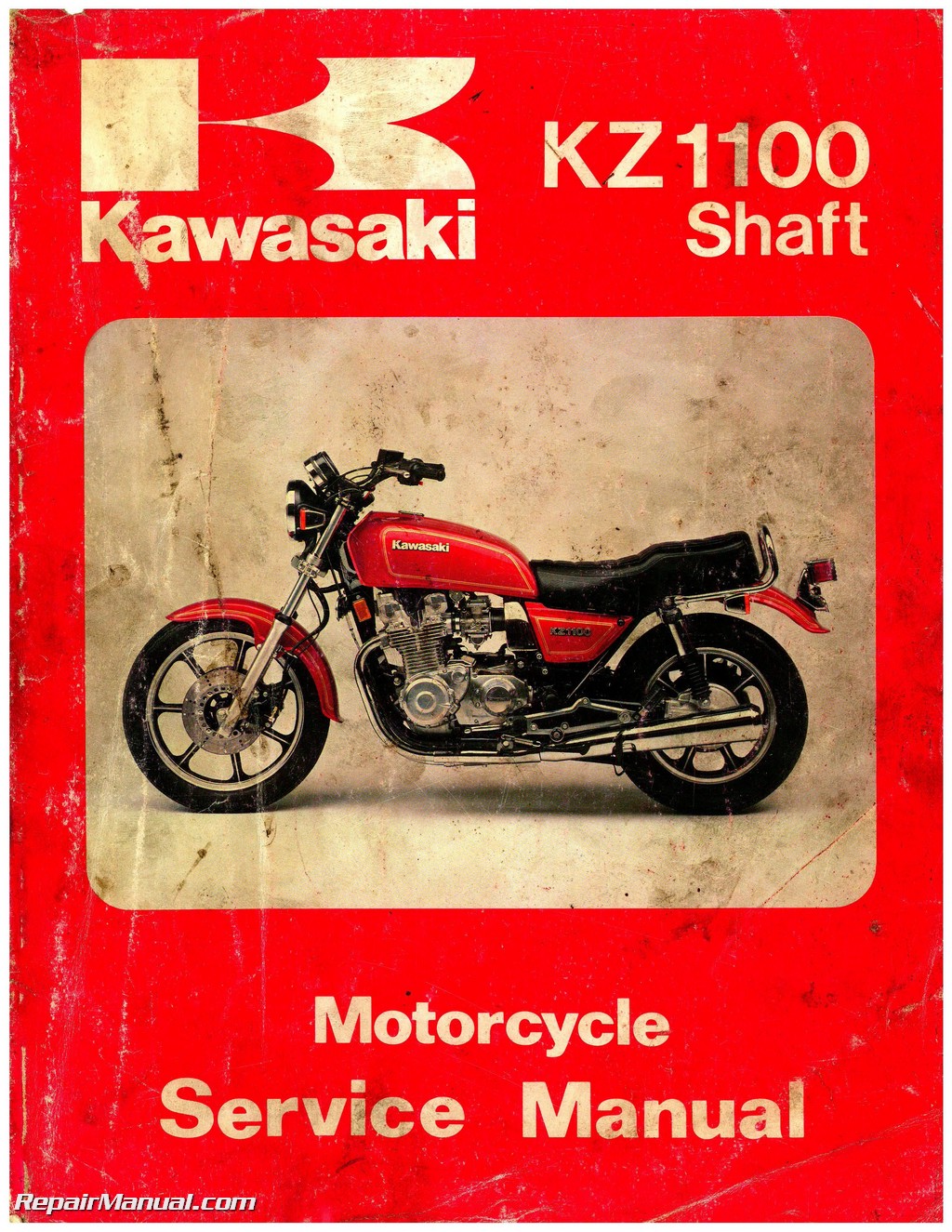
This 294 page, Kawasaki 1981-1983 KZ1100 1984-1985 ZN1100 Shaft Drive Service Manual is a reproduction of the original out of print manual. This printed book provides detailed service information, step-by-step repair instruction and maintenance specifications for 1984-1985 ZN1100B, 1981-1983 KZ1100A, 1982-1983 KZ1100D Kawasaki motorcycles.
This Kawasaki 1981-1983 KZ1100 1984-1985 ZN1100 Shaft Drive Factory Service Manual is designed primarily for use by motorcycle mechanics in a properly equipped shop, although it contains enough detail and basic information to make it useful to the motorcycle user who desires to carry out his own basic maintenance and repair work. Since a certain basic knowledge of mechanics, the proper use of tools, and workshop procedures must be understood in order to carry out maintenance and repair satisfactorily; the adjustments, maintenance, and repair should be carried out only by qualified mechanics whenever the owner has insufficient experience, or has doubts as to his ability to do the work, so that the motorcycle can be operated safely.
In order to perform the work efficiently and to avoid costly mistakes, the mechanic should read this Kawasaki 1981-1983 KZ1100 1984-1985 ZN1100 Shaft Drive Factory Service Manual thoroughly familiarizing himself with the procedures before starting work, and then do the work carefully in a clean area. Whenever special tools or equipment is specified, makeshift tools or equipment should not be used. Precision measurements can only be made if the proper instruments are used, and the use of substitute tools may adversely affect safe operation of the motorcycle.
This Kawasaki 1981-1983 KZ1100 1984-1985 ZN1100 Shaft Drive Factory Service Manual consists of the following major chapters:
1. “General Information” contains general information which will be useful when servicing the motorcycle.
2. “Scheduled Maintenance” gives the procedures for all maintenance which must be done periodically.
3. “Non-Scheduled Maintenance” describes the procedures for inspection, adjustment, and repair which may become necessary unexpectedly or irregularly.
4. “Disassembly” gives teardown sequences required to service most major components. Unless specific instructions are given for assembly and installation, they are performed by reversing the removal/disassembly sequences.
5. “Appendix” in the back of this manual contains miscellaneous information, including an additional considerations for racing, troubleshooting guide, and unit conversion table.
NOTE: Explanation on major changes and additions, that are unique to later year units since the publication of this Kawasaki 1981-1983 KZ1100 1984-1985 ZN1100 Shaft Drive Factory Service Manual, will be added in the end of the text.
Table of Contents
General Information
Before Servicing
Model Indentification
Specifications
Service Data
Torque And Locking Agent
Special Tools
Wiring Diagrams
Scheduled Maintenance
Periodic Maintenance Chart
Engine Oil, Oil Filter
Final Gear Case Oil
Propeller Shaft Joint
Fuel System
Spark Plugs
Ignition System
Valve Clearance
Air Suction Valves (us Model)
Air Cleaner
Throttle Grip
Carburetors
Clutch
Brakes
Brake Light Switches
Steering
Front Fork
Wheels
Swing Arm
Battery
General Lubrication
Bolt And Nut Tightening
Non-scheduled Maintenance – Engine
Fuel Tank, Fuel Tap
Carburetors
Camshafts
Camshaft Chain Chain Guides, Chain Tensioner
Cylinder Head, Valves
Kawasaki Clean Air System (us Model)
Cylinder Block, Pistons
Crankshaft, Connecting Rds
Clutch, Cam Damper
Transmission, Shift Mechanism
Front Bevel Gear Case
Engine Lubrication System
Non-scheduled Maintenance – Chassis
Wheels
Propeller Shaft, Final Gear Case
Brakes
Steering
Frnt Fork
Rear Shck Absrbers
Swing Arm
Non-scheduled Maintenance- Electrical
Battery
Charging System
Ignition System
Electric Starter System
Ignition Switch
Headlight
Turn Signal Circuit, Automatic
Turn Signal Canceling System,
Hazard Warning Circuit
Tail/brake Light
Horn
Fuel Gauge
Electric Speedometer,
Tachometer
Disassembly- Engine
Flow Charts
Disassembly With Engine Installed
Fuel Tank
Fuel Tap
Fuel Level Sender
Air Cleaner Element
Carburetors
Air Cleaner Housing
Vacuum Switch Valve (us Model)
Ignitin Coils
Mufflers
Tp End
Air Suction Valves (us Model)
Cylinder Head Cover
Upper Camshaft-chain Guide
Camshaft Chain Tensioner
Camshafts
Camshaft Sprockets
Cylinder Head
Cylinder Block
Camshaft Chain Guides
Pistons
Piston Rings
Oil Pressure Switch
Breather Cover
Left Side
Front Bevel Gear Case
Neutral Switch
Front Bevel Gear Case
Cam Follower
Cam Spring
Damper Cam
Clutch Release
External Shift Mechanism
Bearing Preloading
Backlash And Contact Adjustment
Alternator Cover
Alternator Stator
Alternator Rotor
Starter Clutch
Starter Motor
Right Side
Pickup Coil Assembly
Timing Advancer
Right Engine Cover
Clutch
Clutch Cam Damper
Bottom End
Oil Filter Element
Bypass Valve
Oil Pan
Engine Oil Pump
Shift Mechanism
Engine Removal
Engine
Disassembly With Engine Removed
Crankcase Split
Transmission
Crankshaft
Camshaft Chain
Crankcase
Disassembly – Chassis
Flow Chart
Wheels
Front Wheel
Speed Sensor
Rear Wheel
Wheel Coupling
Tires
Brakes
Brake Hoses
Discs
Pads
Calipers
Master Cylinders
Cables
Clutch Cable
Throttle Cable
Electrical Equipment
Battery
Battery Housing
Regulator/rectifier
Igniter
Reserve Lighting Device (us Model)
Turn Signal Control Unit
Headlight Unit
Headlight Housing
Headlight Bracket
Turn Signal Assemblies
Speedometer
Tachometer
Fuel Gauge
Ignition Switch/steering Lock Assembly
Brake Light Switches
Handlebar Switch Housing
Starter Lockout Switch
Steering
Handlebar
Steering Stem
Stem Bearings
Suspension, Drive Train
Front Fork
Rear Shock Absorbers
Final Gear Case
Swing Arm
Propeller Shaft
Bearing Preloading
Backlash And The Contact Adjustment
Appendix
Additional Considerations
Fr Racing
Troubleshooting Guide
Unit Conversions
Supplement -1982 Model
This “Supplement – 1982 Model” chapter is designed t be used in conjunction with the front part
f this manual (up t the end f the “Appendix”chapter) The maintenance and repair procedures
described in this chapter are only those that are unique t the 1982 KZ/Z1100A and D Complete and
proper servicing f the 1982 KZ/Z1100A and D therefore requires mechanics t read both this chapter
and the text in front f this chapter
NOTE: Unless otherwise noted, all informations fr the 1982 KZ/Z1100D are the same as for the 1982
KZ/Z1100A
General Information
Model Identification
Specifications (kz/z1100d)
Torque And Locking Agent
Wiring Diagrams – (black and white)
Scheduled Maintenance
Front Fork (kz/z1100d)
Wheels (kz/z1100d)
Non-scheduled Maintenance
Carburetors
Wheels (kz/z1100d)
Front Fork (kz/z1100d)
Rear Shock Absorbers (kz/z1100d)
Electric Starter System
Disassembly
Fuel Tap (kz/z1100d)
Carburetrs (kz/z1100d)
Mufflers (kz/z1100d)
Starter Mtr
Crankcase Split
Rear Wheel (kz/z1100d)
Igniter
Turn Signal Assemblies (kz/z1100d)
Supplement -1983 Mdel
This “Supplement – 1983 Model” chapter is designed to be used in conjunction with the front part
of this manual (up to the end of the 9th chapter) The maintenance and repair procedures described in
this chapter are only those that are unique t the 1983 models Complete and proper servicing f the
1983 models therefore requires mechanics to read both this chapter and the text in front of this
chapter
“NoTE”: The procedures for the 1983 KZ1100L1 are newly included in this chapter Unless otherwise
noted, all informations fr the 1983 KZ1100-L1 are the same as fr the 1983 KZ1100-D2
GENERAL INFoRMATIN
Model Identification (KZ1100L)
Specifications (KZ1100 L)
KZ1100-A3 Wiring Diagram – (black and white)
Z1100-A3 Wiring Diagram – (black and white)
KZ1100-D2 and KZ1100-L1 Wiring Diagram – (black and white)
Z1100-D2 Wiring Diagram – (black and white)
SHEDULED MAINTENANCE
Periodic Maintenance Chart (KZ/Z1100A/D/L)
Front Fork (KZ/Z1100A/D/L)
General Lubrication (KZ/Z1100A/D/L)
NN SCHEDULED MAINTENANCE
Carburetors (KZ/Z1100A/D/L)
Front Fork (KZ1100L)
Rear Shock Absorber (KZ/Z1100A/D/L)
Speedometer (KZ/Z1100A/D/L)
Odometer (KZ/Z1100A/D/L)
Trip Meter (KZ/Z1100A/D/L)
Tach/Voltmeter (KZ/1100A/D)
Automatic Turn Signal Cancelling System
(KZ/Z1100A/D/L)
DISASSEMBLY
Carburetors (KZ/Z1100A)


