Description
This Used Official 2004-2006 Yamaha FZ6 Factory Service Manual provides repair, maintenance and service information for the following models:
2004 Yamaha FZ-6 motorcycles
2005 Yamaha FZ-6 motorcycles
2006 Yamaha FZ-6 motorcycles
This is the same book used by the service department at your local Yamaha dealer for the FZ6-SS FZ6-SSC FZ6-ST FZ6-STC. It has everything in it you need to know in order to repair and service your motorcycle. This book includes LIT-11616-17-50 and supplement LIT-11616-18-43.
2004-2006 Yamaha FZ6 Service Manual Table of Contents
General Information
Specifications
Periodic Checks And Adjustments
Chassis
Engine
Cooling System
Fuel Injection System
Electrical System
Troubleshooting
2004-2006 Yamaha FZ6 Service Manual Index of Topics
Chapter 1 General Information
Motorcycle Identification
Vehicle Identification Number
Model Label
Features
Outline Of Fi System
Fi System
Instrument Function
Important Information
Preparation For Removal And Disassembly
Replacement Parts
Gaskets, Oil Seals And O-rings
Lock Washers/plates And Cotter Pins
Bearings And Oil Seals
Circlips
Checking The Connections
Special Tools
Chapter 2 Specifications
General Specifications
Engine Specifications
Chassis Specifications
Electrical Specifications
Conversion Table
General Tightening Torque Specifications
Tightening Torques
Engine Tightening Torques
Chassis Tightening Torques
Lubrication Points And Lubricant Types
Engine
Chassis
Cooling System Diagrams
Engine Oil Lubrication Chart
Lubrication Diagrams
Cable Routing
Chapter 3 Periodic Checks And Adjustments
Introduction
Periodic Maintenance Chart For The Emission Control System
General Maintenance And Lubrication Chart
Seat
Fuel Tank
Removing The Fuel Tank
Removing The Fuel Pump
Installing The Fuel Pump
Installing The Fuel Tank
Cowlings
Air Filter Case
Battery Box And Battery Box Bracket
Engine
Adjusting The Valve Clearance
Synchronizing The Throttle Bodies
Adjusting The Engine Idling Speed
Adjusting The Throttle Cable Free Play
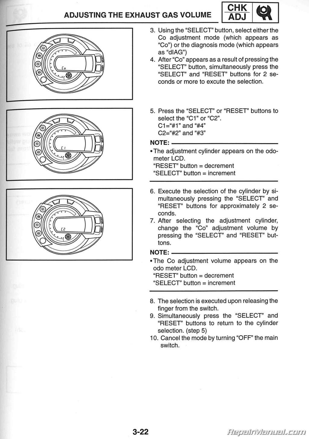
Adjusting The Exhaust Gas Volume
Checking The Spark Plugs
Measuring The Compression Pressure
Checking The Engine Oil Level
Changing The Engine Oil
Measuring The Engine Oil Pressure
Adjusting The Clutch Cable Free Play
Cleaning The Air Filter Element
Checking The Throttle Body Joints
Checking The Fuel And Breather Hoses
Checking The Crankcase Breather Hose
Checking The Exhaust System
Checking The Coolant Level
Checking The Cooling System
Changing The Coolant
Chassis
Adjusting The Front Brake
Adjusting The Rear Brake
Checking The Brake Fluid Level
Checking The Front And Rear Brake Pads
Adjusting The Rear Brake Light Switch
Checking The Front And Rear Brake Hoses
Bleeding The Hydraulic Brake System
Adjusting The Shift Pedal
Adjusting The Drive Chain Slack
Lubricating The Drive Chain
Checking And Adjusting The Steering Head
Checking The Front Fork
Adjusting The Rear Shock Absorber Assembly
Checking The Tires
Checking The Wheels
Checking And Lubricating The Cables
Lubricating The Levers And Pedals
Lubricating The Sidestand
Lubricating The Centerstand
Lubricating The Rear Suspension
Electrical System
Checking And Charging The Battery
Checking The Fuses
Replacing The Headlight Bulbs
Adjusting The Headlight Beams
Chapter 4 Chassis
Front Wheel And Brake Discs
Removing The Front Wheel
Checking The Front Wheel
Checking The Brake Discs
Installing The Front Wheel
Adjusting The Front Wheel Static Balance
Rear Wheel And Brake Disc
Rear Wheel
Rear Brake Disc And Rear Wheel Sprocket
Removing The Rear Wheel
Checking The Rear Wheel
Checking The Rear Wheel Drive Hub
Checking And Replacing The Rear Wheel
Sprocket
Installing The Rear Wheel
Adjusting The Rear Wheel Static Balance
Front And Rear Brakes
Front Brake Pads
Rear Brake Pads
Replacing The Front Brake Pads
Replacing The Rear Brake Pads
Front Brake Master Cylinder
Rear Brake Master Cylinder
Disassembling The Front Brake Master Cylinder Checking The Front And Rear Brake Master
Cylinders
Disassembling The Rear Brake Master Cylinder Assembling And Installing The Front Brake
Master Cylinder
Assembling The Rear Brake Master Cylinder
Front Brake Calipers
Rear Brake Caliper
Disassembling The Front Brake Calipers
Disassembling The Rear Brake Caliper
Checking The Front And Rear Brake Calipers
Assembling And Installing The Front Brake
Calipers
Assembling And Installing The Rear Brake Caliper
Front Fork
Front Fork Legs
Removing The Front Fork Legs
Disassembling The Front Fork Legs
Checking The Front Fork Legs
Assembling The Front Fork Legs
Installing The Front Fork Legs
Handlebar
Removing The Handlebar
Checking The Handlebar
Installing The Handlebar
Steering Head
Under Bracket
Removing The Under Bracket
Checking The Steering Head
Installing The Steering Head
Rear Shock Absorber Assembly
Removing The Rear Shock Absorber Assembly
Handling The Rear Shock Absorber
Disposing Of A Rear Shock Absorber
Checking The Rear Shock Absorber Assembly
Installing The Rear Shock Absorber Assembly
Swingarm And Drive Chain
Removing The Swingarm
Removing The Drive Chain
Checking The Swingarm
Installing The Swingarm
Checking The Drive Chain
Chapter 5 Engine
Engine
Drive Sprocket
Exhaust Pipe
Leads And Hoses
Engine
Installing The Engine
Camshafts
Cylinder Head Cover
Camshafts
Removing The Camshafts
Checking The Camshafts
Checking The Timing Chain, Camshaft Sprockets, And Timing Chain Guides
Checking The Timing Chain Tensioner
Installing The Camshafts
Cylinder Head
Removing The Cylinder Head
Checking The Cylinder Head
Installing The Cylinder Head
Valves And Valve Springs
Removing The Valves
Checking The Valves And Valve Guides
Checking The Valve Seats
Checking The Valve Springs
Checking The Valve Lifters
Installing The Valves
Starter Clutch And Generator
Stator Coil Assembly
Removing The Generator
Removing The Starter Clutch
Checking The Starter Clutch
Installing The Starter Clutch
Installing The Generator
Shift Shaft
Shift Shaft And Stopper Lever
Checking The Shift Shaft
Checking The Stopper Lever
Installing The Shift Shaft
Crankshaft Position Sensor And Pickup Rotor
Removing The Pickup Rotor
Installing The Pickup Rotor
Clutch
Clutch Cover
Clutch
Removing The Clutch
Checking The Friction Plates
Checking The Clutch Plates
Checking The Clutch Springs
Checking The Clutch Housing
Checking The Clutch Boss
Checking The Pressure Plate
Checking The Pull Lever Shaft And Pull Rod Installing The Clutch
Oil Pan And Oil Pump
Removing The Oil Pan
Checking The Oil Pump
Checking The Relief Valve
Checking The Oil Delivery Pipe And Oil Pipe
Checking The Oil Strainer
Checking The Oil Nozzles
Assembling The Oil Pump
Installing The Oil Pump
Installing The Oil Strainer
Installing The Oil Pan
Crankcase
Disassembling The Crankcase
Checking The Crankcase
Checking The Bearings And Oil Seals
Checking The Timing Chain
Assembling The Crankcase
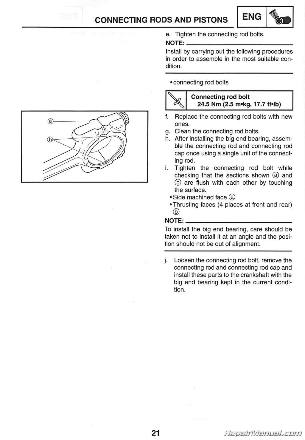
Connecting Rods And Pistons
Removing The Connecting Rods And Pistons
Removing The Crankshaft Assembly
Checking The Cylinder And Piston
Checking The Piston Rings
Checking The Piston Pins
Checking The Big End Bearings (except For Cal)
Checking The Big End Bearings (for Cal)
Installing The Connecting Rod And Piston (except For Cal)
Installing The Connecting Rod And Piston (for Cal)
Crankshaft
Checking The Crankshaft
Checking The Crankshaft Journal Bearings
Installing The Crankshaft
Transmission
Transmission, Shift Drum Assembly And Shift
Forks
Removing The Transmission
Checking The Shift Forks
Checking The Shift Drum Assembly
Checking The Transmission
Installing The Transmission
Chapter 6 Cooling System
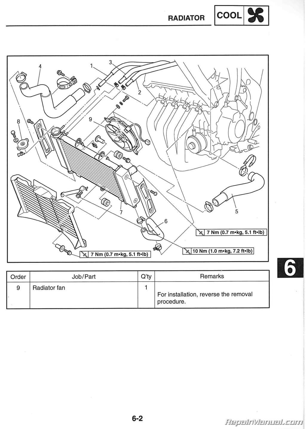
Radiator
Checking The Radiator
Installing The Radiator
Oil Cooler
Checking The Oil Cooler
Installing The Oil Cooler
Thermostat
Checking The Thermostat
Installing The Thermostat
Water Pump
Disassembling The Water Pump
Checking The Water Pump
Assembling The Water Pump
Installing The Water Pump
Chapter 7 Fuel Injection System
Fuel Injection System
Wiring Diagram
Ecu’s Self-diagnostic Function
Alternate Instructions Operation Control (fail-safe Action)
Fail-safe Actions Table
Troubleshooting Chart
Diagnostic Mode
Troubleshooting Details
Throttle Bodies
Injectors
Checking The Injectors
Checking The Throttle Bodies
Checking The Fuel Pump And Pressure Regulator Operation
Checking And Adjusting The Throttle Position Sensor
Air Induction System
Air Injection
Air Cut-off Valve
Air Induction System Diagrams
Checking The Air Induction System
Chapter 8 Electrical System
Electrical Components
Checking Switch Continuity
Checking The Switches
Checking The Bulbs And Bulb Sockets
Types Of Bulbs
Checking The Condition Of The Bulbs
Checking The Condition Of The Bulb Sockets
Checking The Leds
Ignition System
Circuit Diagram
Troubleshooting
Electric Starting System
Circuit Diagram
Starting Circuit Cut-off System Operation
Troubleshooting
Starter Motor
Checking The Starter Motor
Assembling The Starter Motor
Charging System
Circuit Diagram
Troubleshooting
Lighting System
Circuit Diagram
Troubleshooting
Checking The Lighting System
Signaling System
Circuit Diagram
Troubleshooting
Checking The Signaling System
Cooling System
Circuit Diagram
Troubleshooting
Fuel Pump System
Circuit Diagram
Fuel Pump System
Troubleshooting
Checking The Fuel Pump
Self-diagnosis
Troubleshooting
Chapter 9 Troubleshooting
Starting Failures
Engine
Fuel System
Electrical Systems
Incorrect Engine Idling Speed
Engine
Fuel System
Electrical Systems
Poor Medium-and-high-speed Performance
Engine
Fuel System
Faulty Gear Shifting
Shifting Is Difficult
Shift Pedal Does Not Move
Jumps Out Of Gear
Faulty Clutch
Clutch Slips
Clutch Drags
Overheating
Engine
Cooling System
Fuel System
Chassis
Electrical Systems
Overcooling
Cooling System
Poor Braking Performance
Faulty Front Fork Legs
Leaking Oil
Malfunction
Unstable Handling
Faulty Lighting Or Signaling System
Headlight Does Not Come On
Headlight Bulb Burnt Out
Tail/brake Light Does Not Come On
Tail/brake Light Bulb Burnt Out
Turn Signal Does Not Come On
Turn Signal Blinks Slowly
Turn Signal Remains Lit
Turn Signal Blinks Quickly
Horn Does Not Sound

 SKU: M489-2
 SKU: M408
 SKU: M403